
Air conditioning device

a technology of air conditioning and air filter, which is applied in the direction of lighting and heating apparatus, ventilation systems, heating types, etc., can solve the problems of inability to achieve the effect and the air cannot be fully scattered, and achieve the effect of improving comfortability, good performance and comfortable user experien

Inactive Publication Date: 2018-03-01
ZHEJIANG TIANHONG AUTO ACCESSORIES
View PDF2 Cites 0 Cited by
  • Summary
  • Abstract
  • Description
  • Claims
  • Application Information

AI Technical Summary

Benefits of technology

[0003]An object of the present invention is to provide an air conditioning device which allows a uniform outflow of air and has good performance when in use.
[0013]1) in the present invention, air is blown out through the air vents provided on the panel that are in communication with the cavity, which allows a uniform and gentle outflow of air and brings a comfortable user experience;
[0014]2) the air vents provided in the present invention are of a bellmouthed structure with a diameter decreasing from the bottom to the top, and can achieve the effect of blowing cold air, thus having a cooling effect, making people feel much cooler especially in summer;
[0015]3) the protrusions or ribs provided in the present invention can ensure that the air vents can blow air properly and present good performance when in use, even if the panel is covered; and
[0016]4) the protrusions provided on the panel of the present invention has a massaging effect, which improves the comfortability.

Problems solved by technology

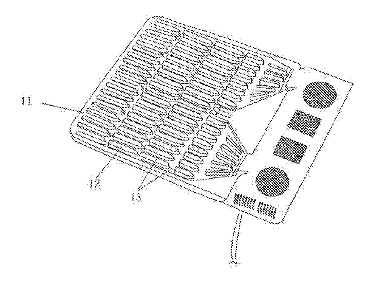
However, the air conditioning device of such a structure has the following defects: on one hand, the air blown out by such a structure is natural air, and cannot achieve the effect of cooling air, especially in summer; and on the other hand, since the air channels 13 are open, the air cannot be fully scattered.

Method used


Image

  • Air conditioning device
  • Air conditioning device
  • Air conditioning device

Examples


Embodiment Construction

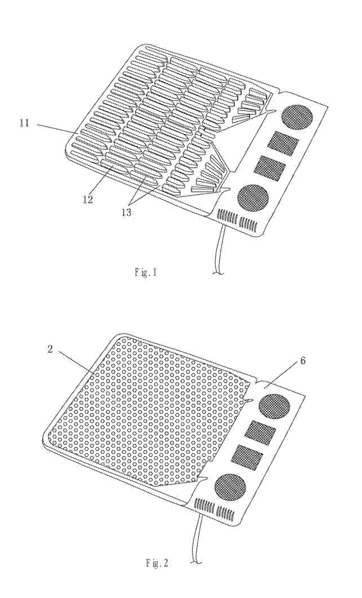
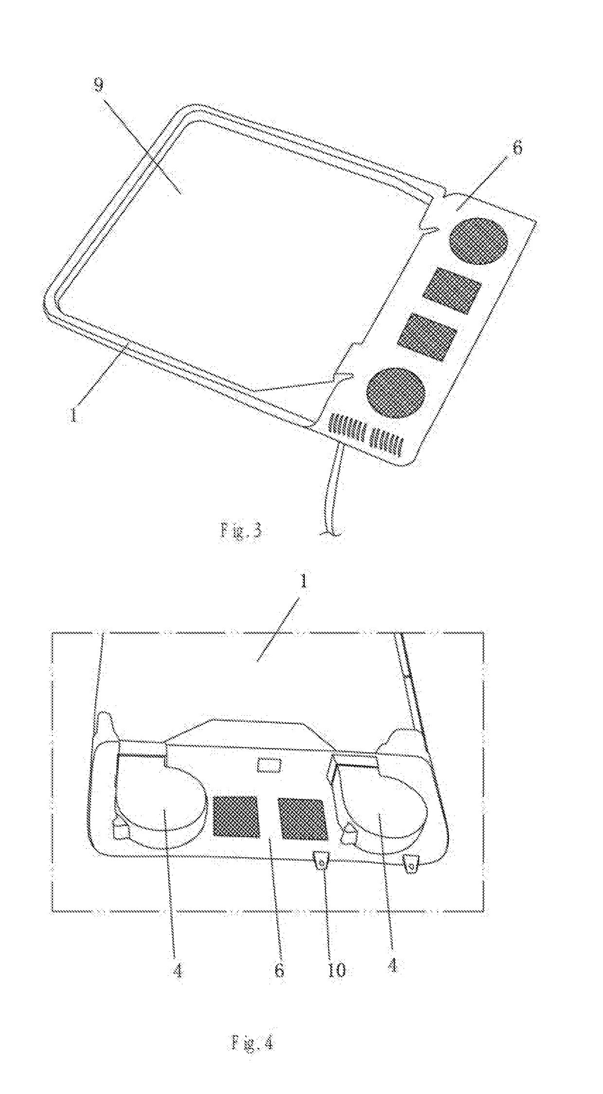
[0024]The present invention is further described with particular embodiments below, see FIGS. 2-7.

[0025]n air conditioning device comprises a baseplate 1 provided with a recess 8, wherein a panel 2 is provided on the baseplate 1, the panel 2 and the recess 8 form an independent cavity 3, one or more fans 4 are provided at one end of the baseplate 1, each fan 4 having an air outlet in communication with the cavity 3, and a reasonable number of air vents 5 are provided on the panel 2. In the present embodiment, the air vents 5 are provided on the entire panel 2. The specific number of the air vents 5 is set depending on the actual situation. The number of the fan(s) 4 is likewise set depending on the actual situation, and two fans 4 are provided in the present embodiment. The fans 4 can be connected to a mains power supply via a plug or be connected to a power supply in an automobile via an automobile plug.

[0026]The working principle of the present invention is as follows:

[0027]he fan...


PUM


Abstract

The present invention relates to an air conditioning device, comprising a baseplate provided with a recess, wherein a panel is provided on the baseplate, the panel and the recess form an independent cavity, one or more fans are provided at one end of the baseplate, each fan having an air outlet in communication with the cavity, and a reasonable number of air vents are provided on the panel, the one or more fans blowing air into the cavity and then the air blowing out of the air vents. In the present invention, air is blown outwards through the air vents provided on the panel that are in communication with the cavity, which allows a uniform and gentle outflow of air and brings a comfortable user experience.

Description

FIELD OF THE INVENTION[0001]The present invention relates to an air conditioning device.BACKGROUND OF THE INVENTION[0002]In some occasions, it is necessary to divert airflow of a fan such that the air is blown out over a wider range. Common air conditioning devices at present have a structure (as shown in FIG. 1) which comprises a baseplate 11, an upper surface of the baseplate 11 being provided with several strip-shaped protrusions 12 arranged in rows and columns, air channels 13 being formed between the strip-shaped protrusions 12, and the air channels 13 serving to guide the airflow. The air blown out by the fan is scattered via the air channels 13, so that the air outflow area is increased. However, the air conditioning device of such a structure has the following defects: on one hand, the air blown out by such a structure is natural air, and cannot achieve the effect of cooling air, especially in summer; and on the other hand, since the air channels 13 are open, the air cannot ...

Claims


Application Information

Patent Timeline
Patent Type & Authority Applications(United States)
IPC IPC(8): B60H1/34
CPCB60H1/3407F04D25/08F04D29/002B60H1/00264B60H1/2225F24H3/0405F24F7/007
Inventor CHEN, TONGCHAI
Owner ZHEJIANG TIANHONG AUTO ACCESSORIES
Learn More