Lithographic apparatus

a technology of lithographic apparatus and lithography, applied in the field of lithographic apparatus, can solve problems such as unfavorable and unpredictable effects

Inactive Publication Date: 2018-03-01
ASML NETHERLANDS BV
View PDF5 Cites 0 Cited by
  • Summary
  • Abstract
  • Description
  • Claims
  • Application Information

AI Technical Summary

Benefits of technology

[0008]Accordingly, it would be advantageous, for example, to provide a lithographic apparatus in which a measurement at substrate level may be performed without reduction in throughput.

Problems solved by technology

This requires additional or more powerful motors and turbulence in the liquid may lead to undesirable and unpredictable effects.

Method used


Image

  • Lithographic apparatus
  • Lithographic apparatus
  • Lithographic apparatus

Examples


Embodiment Construction

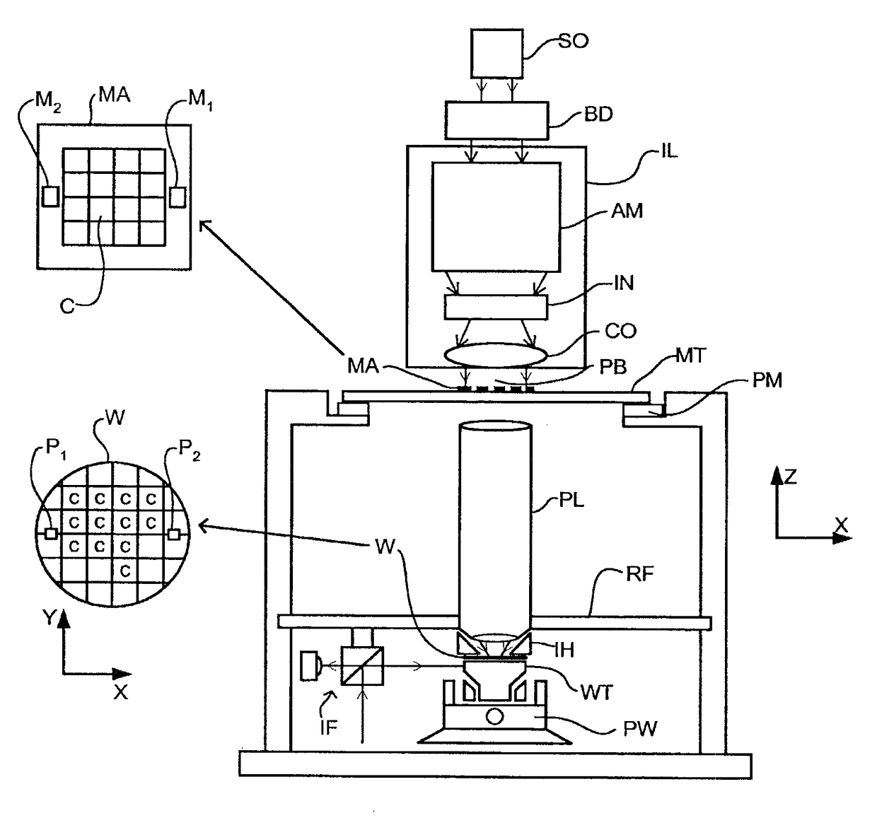
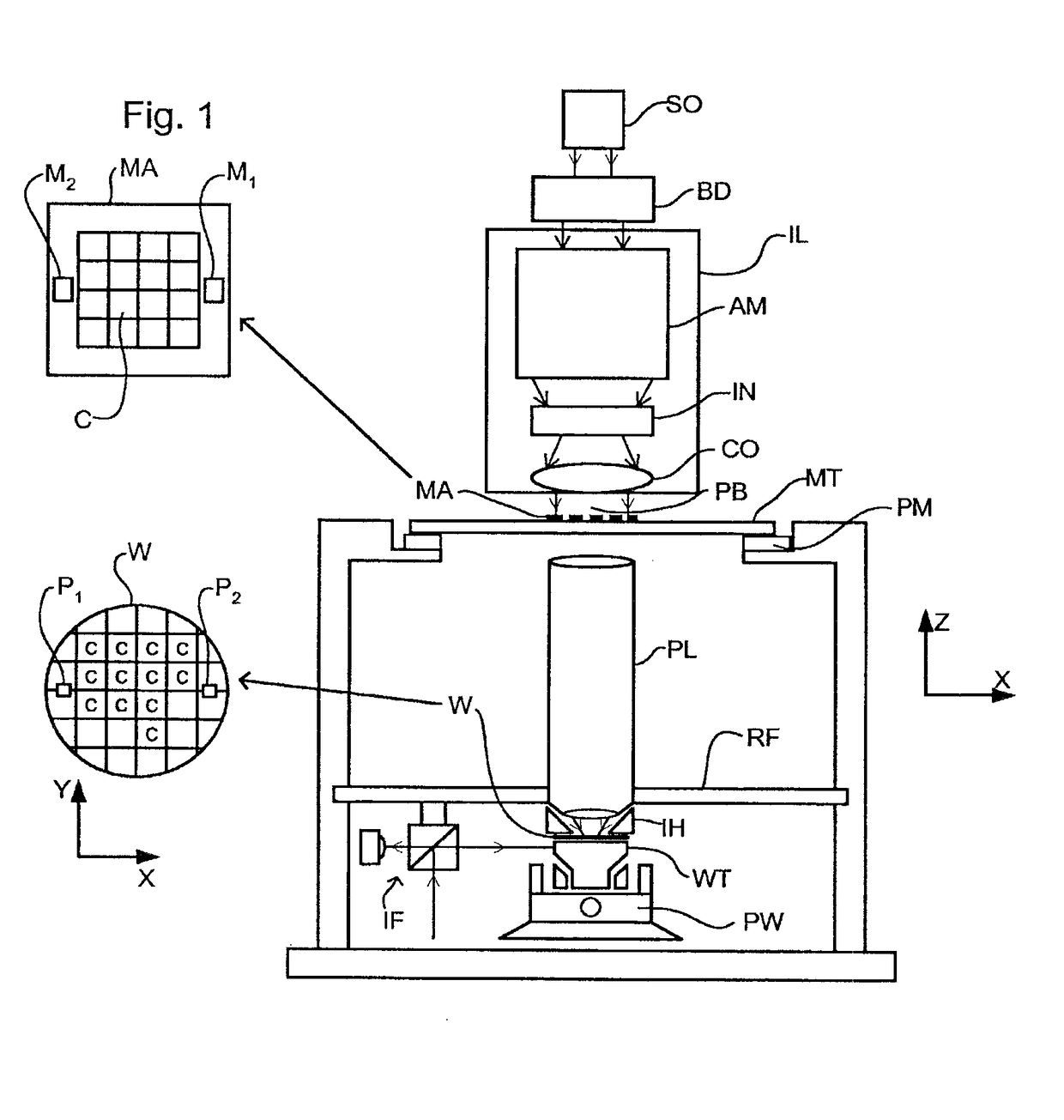
[0029]FIG. 1 schematically depicts a lithographic apparatus according to one embodiment of the invention. The apparatus comprises:[0030]an illumination system (illuminator) IL configured to condition a radiation beam PB (e.g. UV radiation or DUV radiation).[0031]a support structure (e.g. a mask table) MT constructed to support a patterning device (e.g. a mask) MA and connected to a first positioner PM configured to accurately position the patterning device in accordance with certain parameters;[0032]a substrate table (e.g. a wafer table) WT constructed to hold a substrate (e.g. a resist-coated wafer) W and connected to a second positioner PW configured to accurately position the substrate in accordance with certain parameters; and[0033]a projection system (e.g. a refractive projection lens system) PL configured to project a pattern imparted to the radiation beam PB by patterning device MA onto a target portion C (e.g. comprising one or more dies) of the substrate W.

[0034]The illumin...


PUM

PropertyMeasurementUnit
wavelengthaaaaaaaaaa

Abstract

A lithographic apparatus includes a first table to support a substrate; a second table, not being configured to support a substrate, including a sensor unit to sense a property of a patterned beam of radiation from a projection system, the second table to move under the projection system when the first table is moved out from under the projection system during a substrate exchange, the first and second tables being independently movable from each other; and a liquid supply system to supply a liquid to a space between the projection system and the substrate, the first table, and / or the second table, wherein the second table is configured to provide a confining surface at a bottom of a liquid confinement structure when the first table is removed from under the projection system so as to prevent the liquid from leaking out into the remainder of the lithographic apparatus.

Description

CROSS-REFERENCE TO RELATED APPLICATIONS[0001]This application is a continuation of U.S. application Ser. No. 15 / 216,670, filed Jul. 21, 2016, which is a continuation of co-pending U.S. patent application Ser. No. 14 / 661,929, filed on Mar. 18, 2015, now U.S. Pat. No. 9,417,535, which is a continuation of U.S. patent application Ser. No. 14 / 500,386, filed on Sep. 29, 2014, now U.S. Pat. No. 9,329,494, which is a continuation of U.S. patent application Ser. No. 13 / 188,096, filed on Jul. 21, 2011, now U.S. Pat. No. 9,116,443, which is a continuation of U.S. patent application Ser. No. 12 / 327,414, filed on Dec. 3, 2008, now U.S. Pat. No. 8,233,137, which is a continuation of U.S. patent application Ser. No. 11 / 015,766, filed on Dec. 20, 2004, now U.S. Pat. No. 7,528,931. The contents of each of the foregoing applications are incorporated herein in their entirety by referenceFIELD[0002]The present invention relates to a lithographic apparatus and a method for manufacturing a device.BACKGR...

Claims


Application Information

Patent Timeline
Patent Type & Authority Applications(United States)
IPC IPC(8): G03F7/20
CPCG03F7/70883G03F7/70341G03F7/7075
Inventor MODDERMAN, THEODORUS MARINUS
Owner ASML NETHERLANDS BV
Why Eureka
Try Eureka