
Rear crash safety profile

a technology for crash safety and profile, applied in the direction of electric propulsion mounting, bumpers, elastic dampers, etc., can solve the problems of affecting the safety of electric vehicles

Active Publication Date: 2018-03-08
THUNDER POWER ELECTRIC VEHICLE LTD
View PDF0 Cites 6 Cited by
  • Summary
  • Abstract
  • Description
  • Claims
  • Application Information

AI Technical Summary

Benefits of technology

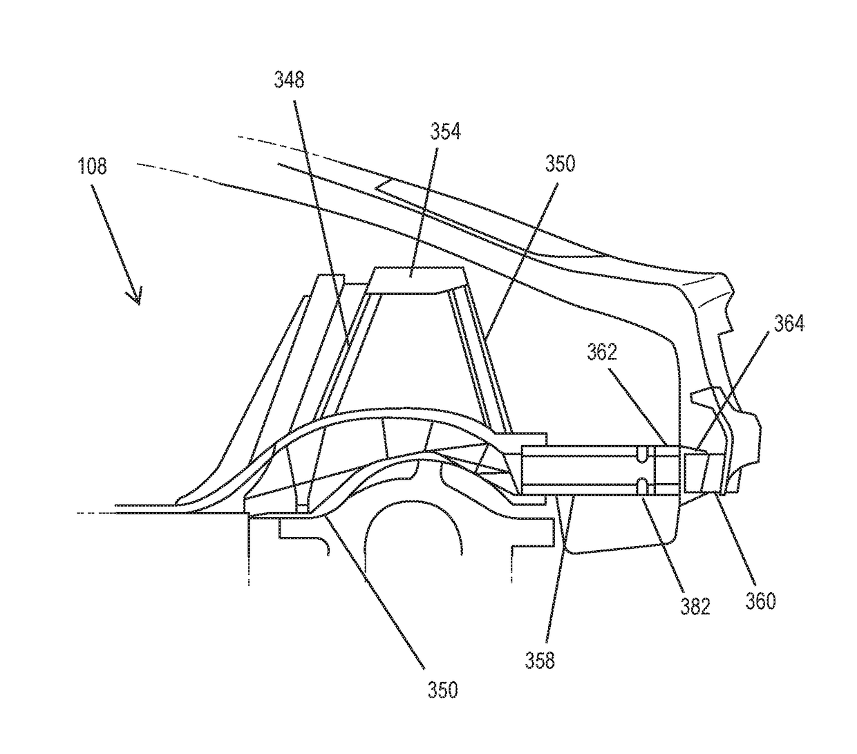
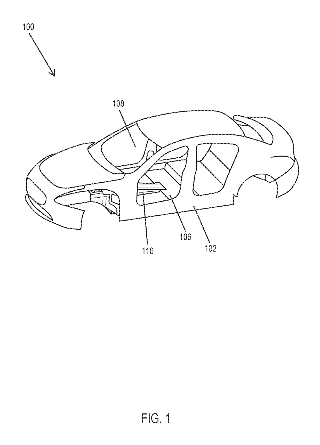
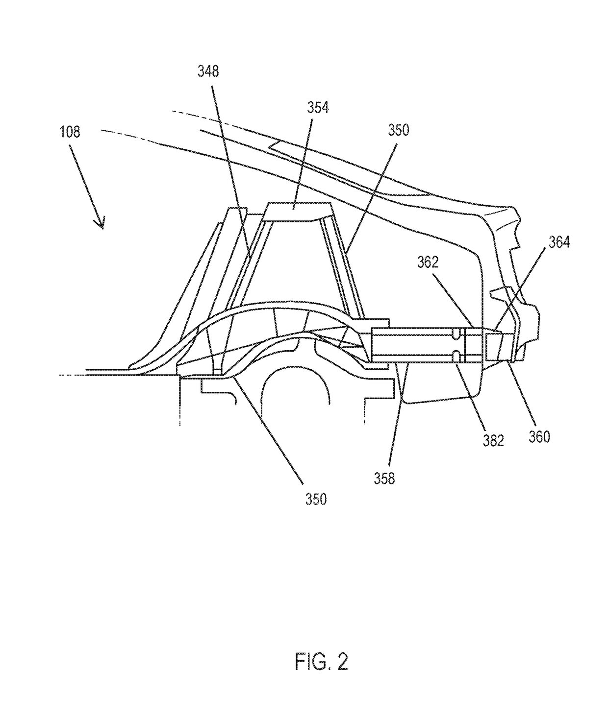
This patent describes a rear impact system for an electric vehicle that includes a left crash beam and a right crash beam that are connected to the rear portion of the vehicle's wheel arches and extend to the rear bumper. The crash beams have a generally octagonal shape and are reinforced with internal ribs that extend in a longitudinal direction. The system is designed to absorb impact and transfer the force of the impact to the vehicle's rear wheel arches, resulting in a safer and more effective response to rear collisions.

Problems solved by technology

There are many problems unique to electric vehicles, oftentimes due to the presence of large and / or numerous batteries used to power the electric motor and other components of the vehicle.
These batteries are often bulky, and add significant weight to the vehicles.
These considerations present challenges in designing a particularly efficient and practical electrical vehicle.
Additionally, these batteries may be particularly susceptible to damage during a collision.
Damage to a battery may be especially dangerous by presenting a fire and / or corrosive hazard.
As such, protecting the batteries from damage remains a difficult challenge unique to the field of electric vehicles.

Method used


Image

  • Rear crash safety profile
  • Rear crash safety profile
  • Rear crash safety profile

Examples


Embodiment Construction

[0019]The subject matter of embodiments of the present invention is described here with specificity to meet statutory requirements, but this description is not necessarily intended to limit the scope of the claims. The claimed subject matter may be embodied in other ways, may include different elements or steps, and may be used in conjunction with other existing or future technologies. This description should not be interpreted as implying any particular order or arrangement among or between various steps or elements except when the order of individual steps or arrangement of elements is explicitly described.

[0020]The systems and methods described herein relate generally to improvements for electric vehicles. Due to the size and weight considerations of the batteries required to power such vehicles, as well as the need to make electric vehicles as safe as possible, each component within the electric vehicles must be designed with particular characteristics in mind. Specifically, con...


PUM


Abstract

A rear impact system for an electric vehicle includes a left crash beam coupled with a rear portion of a rear wheel arch of the electric vehicle and extending to a rear bumper of the electric vehicle and a right crash beam coupled with the rear portion of the rear wheel arch and extending to the rear bumper. Each of the left crash beam and the right crash beam defines a generally octagonal shape. Each of the left crash beam and the right crash beam defines an interior comprising a plurality of ribs extending in a longitudinal direction.

Description

CROSS-REFERENCE TO RELATED APPLICATION[0001]The present application claims the benefit of U.S. Provisional Application No. 62 / 384,298, filed Sep. 7, 2016, the entire contents of which are hereby incorporated by reference for all purposes.BACKGROUND OF THE INVENTION[0002]There are many problems unique to electric vehicles, oftentimes due to the presence of large and / or numerous batteries used to power the electric motor and other components of the vehicle. These batteries are often bulky, and add significant weight to the vehicles. These considerations present challenges in designing a particularly efficient and practical electrical vehicle. Additionally, these batteries may be particularly susceptible to damage during a collision. Damage to a battery may be especially dangerous by presenting a fire and / or corrosive hazard. As such, protecting the batteries from damage remains a difficult challenge unique to the field of electric vehicles.[0003]Vehicle manufacturers have added a numb...

Claims


Application Information

Patent Timeline
IPC IPC(8): B62D21/15B62D21/02B62D25/20
CPCB62D21/152B60K2001/0416B62D25/2027B62D21/02B60R19/34B62D25/08B62D25/087B62D29/008F16F7/12
Inventor MAIER, JENS
Owner THUNDER POWER ELECTRIC VEHICLE LTD
Learn More