This helps you quickly interpret patents by identifying the three key elements:
Problems solved by technology
Method used
Benefits of technology
Benefits of technology
[0004]In the conventional configuration, however, the flight powering battery that can be carried on the flying object is required to be light i
Problems solved by technology
In the conventional configuration, however, the flight powering battery that can be carried on th
Method used
Image
Click on the blue label to locate the original text in one second.
Reading with bidirectional positioning of images and text.
Examples
Example
First Exemplary Embodiment
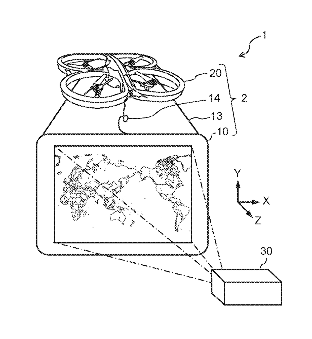
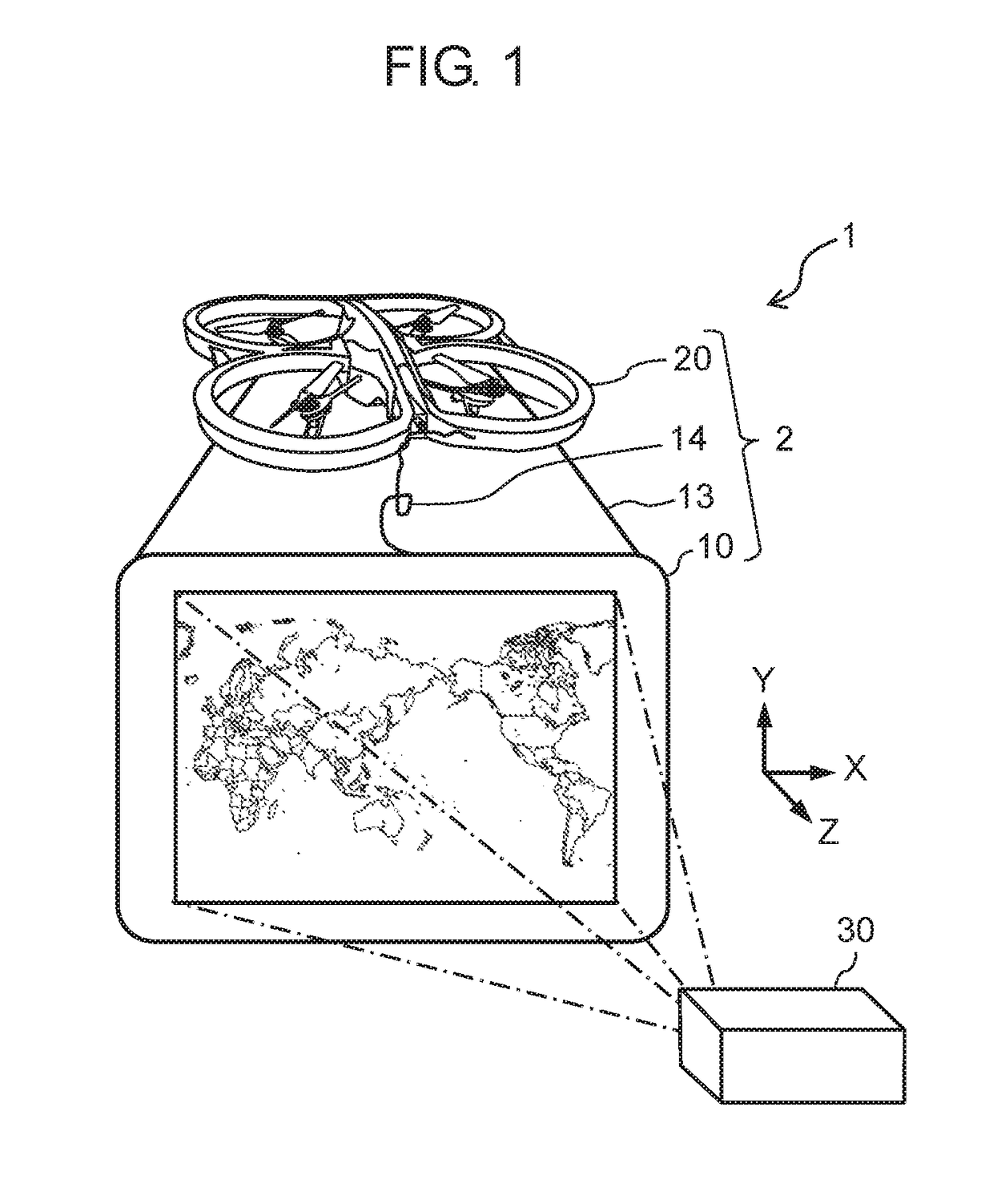
[0021]First, a configuration of image projection system 1 of the present disclosure will be described. FIG. 1 is a schematic diagram illustrating image projection system 1 in accordance with a first exemplary embodiment.
[0022]As shown in FIG. 1, image projection system 1 of the present disclosure is configured by screen device 2 having flying object 20 and screen 10 supported by flying object 20, and image projection device 30. Screen 10 is supported on flying object 20 with support members 13 so that screen 10 can fly in the sky in a horizontal direction (a X direction), a vertical direction (a Y direction) and a projection direction from image projection device 30 to screen 10 (a Z direction). Screen 10 and flying object 20 are electrically connected to each other through cable 14. Screen 10 receives image light projected from image projection device 30. Flying object 20 can be supplied with electric power from screen 10. Referring to FIG. 1, the rightwar...
Example
Second Exemplary Embodiment
[0056]In the first exemplary embodiment, flying object 20 is moved or rotated to optimize the electric power generated by photoelectric conversion elements 11 and the image light projected position on screen 10. In the second exemplary embodiment, the brightness or the projection direction of the image projected by image projection device 30 is changed to optimize the electric power generated by photoelectric conversion elements 11 and the image light projected position on screen 10. The same components as those of the first exemplary embodiment will be respectively indicated by the same reference marks, and description on them will be omitted.
[0057]Operations of image projection system 1 in accordance with the present disclosure will be described. FIG. 10 is a flowchart illustrating operations of image projection system 1 in accordance with the second exemplary embodiment.
[0058]Steps S51 through S58 are the same as those in the first exemplary embodiment....
Example
Third Exemplary Embodiment
[0065]In the second exemplary embodiment, flying object 20 transmits the instruction signal to image projection device 30 to change the projection condition of the image light. In the third exemplary embodiment, flying object 20 transmits the total value of electric power and the evaluation electric power values to image projection device 30, and image projection device 30 changes the projection condition of the image light. The same components as those of the first exemplary embodiment are respectively indicated by the same reference marks, and description on them will be omitted.
[0066]Operations of image projection system 1 in accordance with the present disclosure will be described. FIG. 11 is a flowchart illustrating operations of image projection system 1 in accordance with the third exemplary embodiment.
[0067]Steps S51 through S58 are the same as those in the first exemplary embodiment. Hereinafter, only flows related to steps S81 through S84, which a...
PUM
Abstract
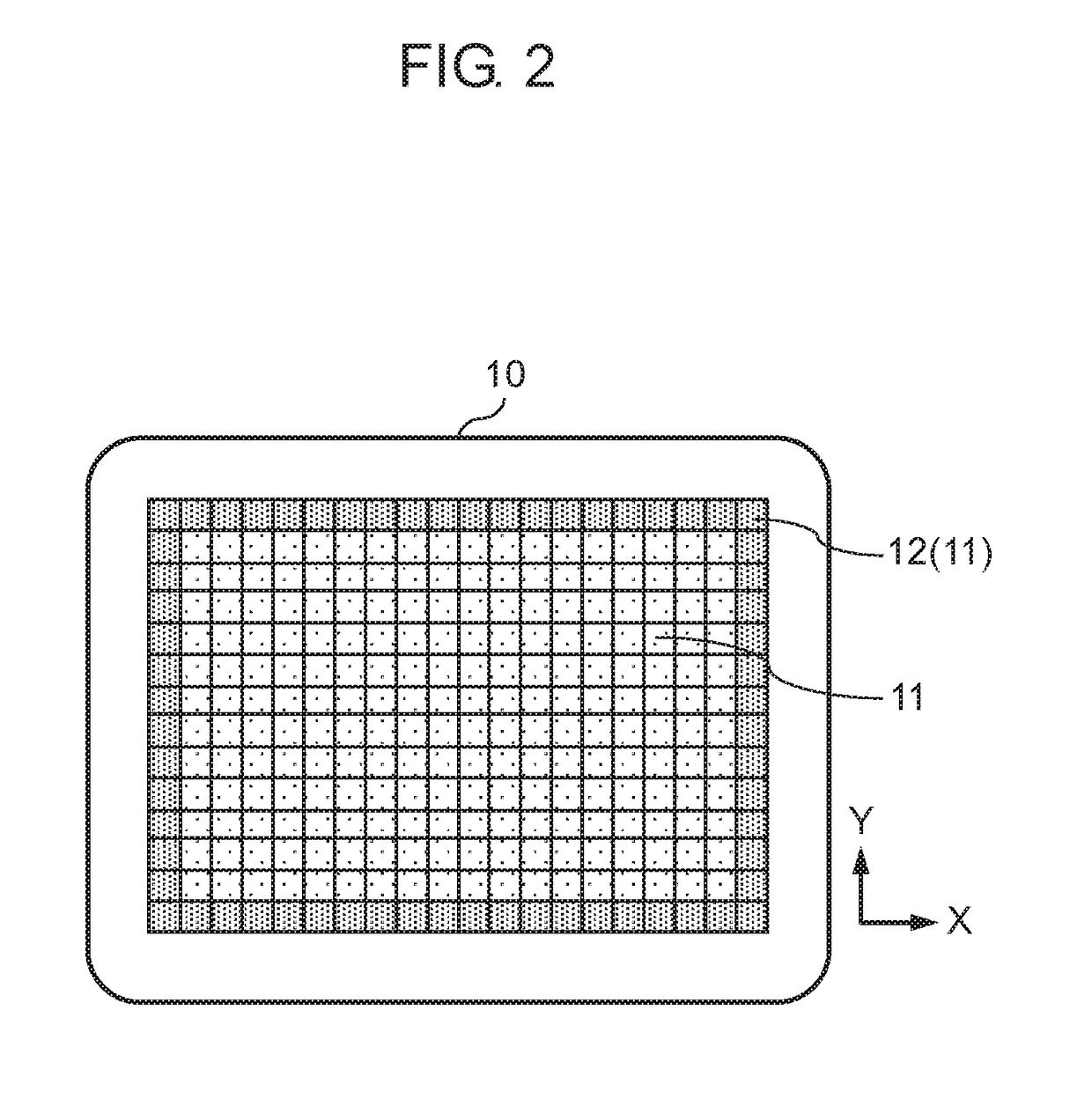
A screen device in accordance with the present disclosure comprises: a screen that has a plurality of photoelectric conversion elements and receives image light from an image projection device; a power supply unit that supplies electric power generated by photoelectric conversion from the received image light by the plurality of photoelectric conversion elements; a flying object that supports the screen and flies on the electric power supplied from the power supply unit; and a flight controller that controls flight of the flying object. An image projection system in accordance with the present disclosure comprises: the screen device; and the image projection device that projects the image light onto the screen.
Description
TECHNICAL FIELD[0001]The present disclosure relates to a screen device and an image projection system which are configured such that a flying object flying in the sky supports a screen which receives image light from an image projection device.BACKGROUND ART[0002]Such conventional screen device and image projection system are known that use a flying object flying in the sky to support a screen which receives image light from an image projection device. The flying object is powered by electric power supplied from a flight power battery to fly (see PTL 1, for example).CITATION LISTPatent Literature[0003]PTL 1: Unexamined Japanese Patent Publication No. 2005-119402SUMMARY OF THE INVENTION[0004]In the conventional configuration, however, the flight powering battery that can be carried on the flying object is required to be light in weight, so that the capacity of the battery is limited. Accordingly, the flying object can fly for only a short time (ten and several minutes).[0005]An objec...
Claims
Application Information
Patent Timeline
Application Date:The date an application was filed.
Publication Date:The date a patent or application was officially published.
First Publication Date:The earliest publication date of a patent with the same application number.
Issue Date:Publication date of the patent grant document.
PCT Entry Date:The Entry date of PCT National Phase.
Estimated Expiry Date:The statutory expiry date of a patent right according to the Patent Law, and it is the longest term of protection that the patent right can achieve without the termination of the patent right due to other reasons(Term extension factor has been taken into account ).
Invalid Date:Actual expiry date is based on effective date or publication date of legal transaction data of invalid patent.

