
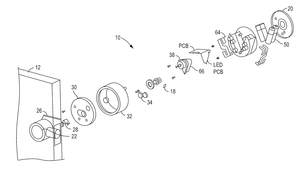
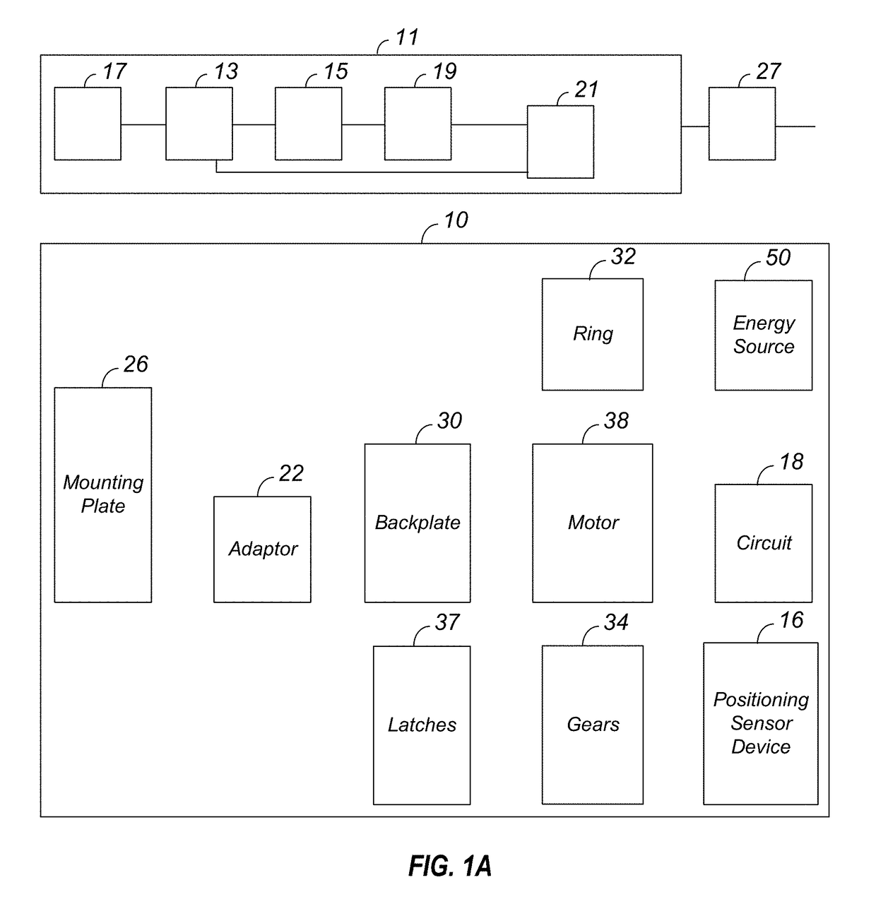
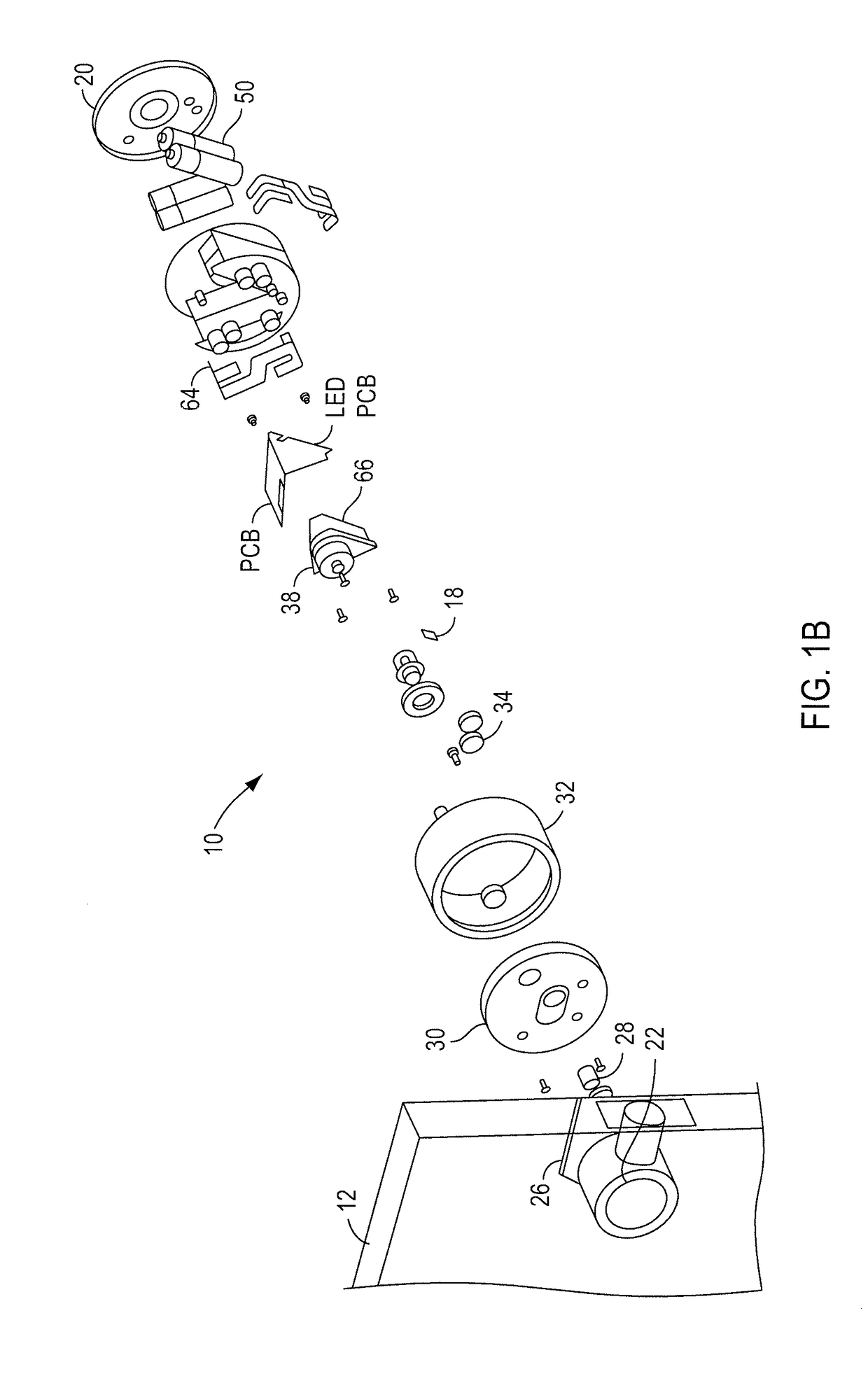
Video recording triggered by a smart lock device

a smart lock and video recording technology, applied in alarm locks, television systems, instruments, etc., can solve the problems of inability to send such an email, the difficulty of installing multiple cameras inside and outside a residence or commercial, and the vulnerability of such a system

Active Publication Date: 2018-03-15
AUGUST HOME
View PDF11 Cites 33 Cited by
  • Summary
  • Abstract
  • Description
  • Claims
  • Application Information

AI Technical Summary

Benefits of technology

The invention is an intelligent door lock system that includes a camera to record information about the door lock status. The system can communicate directly with the camera either through Bluetooth or wired connections. The camera can be retrofitted to existing door lock systems or used in new installations. The technical effects of this invention include improved security, convenience, and improved user experience.

Problems solved by technology

Such cabling makes it difficult to install the multiple cameras inside and outside a residence or commercial because of routing of such long cabling between a dwelling user, resource owner, or end-user, resource owner, or end-user accessible box and cameras.
However, there is much vulnerability in such a system.
If internet is not working at the time of intrusion because phone or internet cables are externally cut, then no such email could be send.
One of the disadvantages of such a security system is that if internet access deliberately interrupted at the time of a security event, then it is not possible to stream the data for the event to the remote PC for recording.
Furthermore, such a system requires continuous stream of multiple video streams over local and wide area networks, which places a considerably load on such networks, thus causing unreliable operations and slowing other network activity.
Cabled systems using Ethernet cabling also require difficult cabling of multiple camera units.
Thus, it becomes difficult and unreliable to transfer plurality of live compressed video stream in real-time without interruptions.
However, such systems consume energy.

Method used


Image

  • Video recording triggered by a smart lock device
  • Video recording triggered by a smart lock device
  • Video recording triggered by a smart lock device

Examples


example 1

Encryption Example 1

[0454]Terms:

[0455]The following terms are used: encryption function: e (key, block)

[0456]decryption function: d(key, block)

[0457]random number function r(number)

[0458]The handshake key will be called Kh

[0459]The generated session key, Ks

[0460]A 32-bit constant used during Initialization, IC

[0461]A 32-bit constant used during Initialization, RC

[0462]mFooBar means foobar for the mobile device 210

[0463]lFooBar means foobar for the lock (it's an el not an eye).

[0464]Communication is initialized by generating a session nonce (Ns) on the mobile device 210. This session nonce is encrypted using a handshake key (Kh). The handshake key is a shared secret known to the lock and to the entity encrypting the nonce. The lock then modifies the nonce and returns the modified value to the mobile device 210. The entity that has the handshake key then decrypts the session key and the mobile device 210 uses that to encrypt subsequent communication.

[0465]Factory Initialization

[0466]W...


PUM


Abstract

An intelligent door lock system coupled to a door at a dwelling. a door status device is at the dwelling. The door status device is coupled to a drive shaft of a lock device to assist in locking and unlocking a lock of a lock device at the door. The lock device is coupled to the door status device and includes a bolt. An engine, an energy source and a memory are coupled together. A camera is coupled to or part of the intelligent door lock system. The camera is configured to record in response to door lock status.

Description

CROSS REFERENCE TO RELATED APPLICATIONS[0001]This application claims the priority benefit of all of the following: a Continuation in part of Ser. No. 15 / 497,383, filed Apr. 26, 2017, which is a U.S. Provisional Patent Application No. 62 / 481,797, filed Apr. 5, 2017, a Continuation in part of patent application Ser. No. 15 / 497,327 filed Apr. 26, 2017, which is a Continuation in part of patent application Ser. No. 15 / 463,022, filed Mar. 20, 2017, which is a Continuation in part of patent application Ser. No. 15 / 410,845, filed Jan. 20, 2017, which is a Continuation of patent application Ser. No. 15 / 066,210, filed Mar. 10, 2016, which is a Continuation of patent application Ser. No. 14 / 205,608, filed Mar. 12, 2014, which is a U.S. Provisional Patent Application No. 61 / 800,937, filed Mar. 15, 2013, which is a U.S. Provisional Patent Application No. 61 / 801,335, filed Mar. 15, 2013, which is a U.S. Provisional Patent Application No. 61 / 801,294, filed Mar. 15, 2013, which is a Continuation o...

Claims


Application Information

Patent Timeline
IPC IPC(8): E05B47/00H04N7/18G08B29/18E05B45/06E05B47/02E05B55/12E05C1/00G07C9/00G08B13/196
CPCE05B2047/0072Y10T292/1021E05B2047/0048E05B47/00E05B45/06E05B2045/069E05B55/12E05B2047/0022E05B47/026E05B2047/002E05B2047/0058E05B2047/0091E05B2047/0095G07C9/00309G07C9/00944G07C2209/62G08B29/185G08B13/19695H04N7/186E05B47/0012E05B47/0001E05C1/004E05B47/0038E05B63/0065G08B13/08E05B2047/0065E05B2047/0068E05B2047/0069G07C2009/00769G07C2009/0096E05B2063/0091G08B13/19656H04N23/661
Inventor JOHNSON, JASONLETOURNEUR, HERVE JACQUES CLEMENTUNADKAT, TEJASHDOW, CHRISTOPHER
Owner AUGUST HOME
Learn More