
Lighting device for producing a supplemental beam

a technology of supplemental beams and light sources, which is applied in the direction of fixed installations, lighting and heating apparatuses, instruments, etc., can solve the problems of limited benefit of high beams, complex mechanisms of systems, and high cost, and achieve the effect of increasing the intensity of primary beams

Active Publication Date: 2018-03-15
VALEO NORTH AMERICA
View PDF1 Cites 3 Cited by
  • Summary
  • Abstract
  • Description
  • Claims
  • Application Information

AI Technical Summary

Benefits of technology

The invention provides a vehicle lighting device with a high performance beam that does not exceed regulatory limits, such as the SAE H-V limit of 75,000 candelas. The device includes a supplemental lighting system that produces a complementary beam that is combined with the primary beam to create a supplemented beam pattern. The complementary beam has a complementary distribution that adds less light in certain areas, but increases the intensity in other areas. The device also includes a lens that shapes the beams and a housing to support the lens. The invention also provides a method for creating a high performance beam that exceeds the predetermined maximum intensity but does not exceed the predetermined area of maximum intensity. The vehicle lighting device can use an LED and a beam splitter or light guide to generate the complementary beam. The technical effects of the invention include improved performance, reduced regulation limits, and a more complex optical design.

Problems solved by technology

Because the maximum high beam output is limited to, for example, 75,000 candelas, the use of supplemental high beam lamps that add additional light to the high beam is of limited benefit because the combination of a supplemental beam with a high beam cannot exceed the 75,000 candelas limit.
Some prior art lighting systems, such as adaptive driving beam (ADB) headlamp systems, may be considered to supplement the high beam, but these systems were typically complex mechanisms and sophisticated, sometimes requiring pixel switching or other mechanisms that were necessary to supplement the high beam.

Method used


Image

  • Lighting device for producing a supplemental beam
  • Lighting device for producing a supplemental beam
  • Lighting device for producing a supplemental beam

Examples


Embodiment Construction

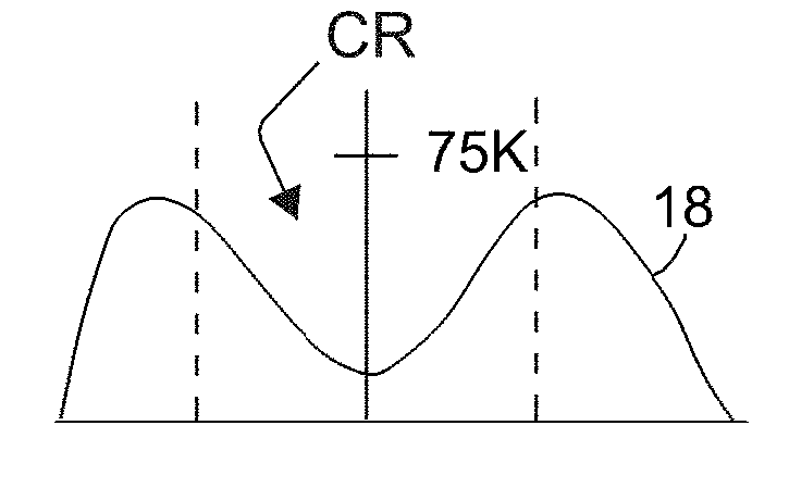
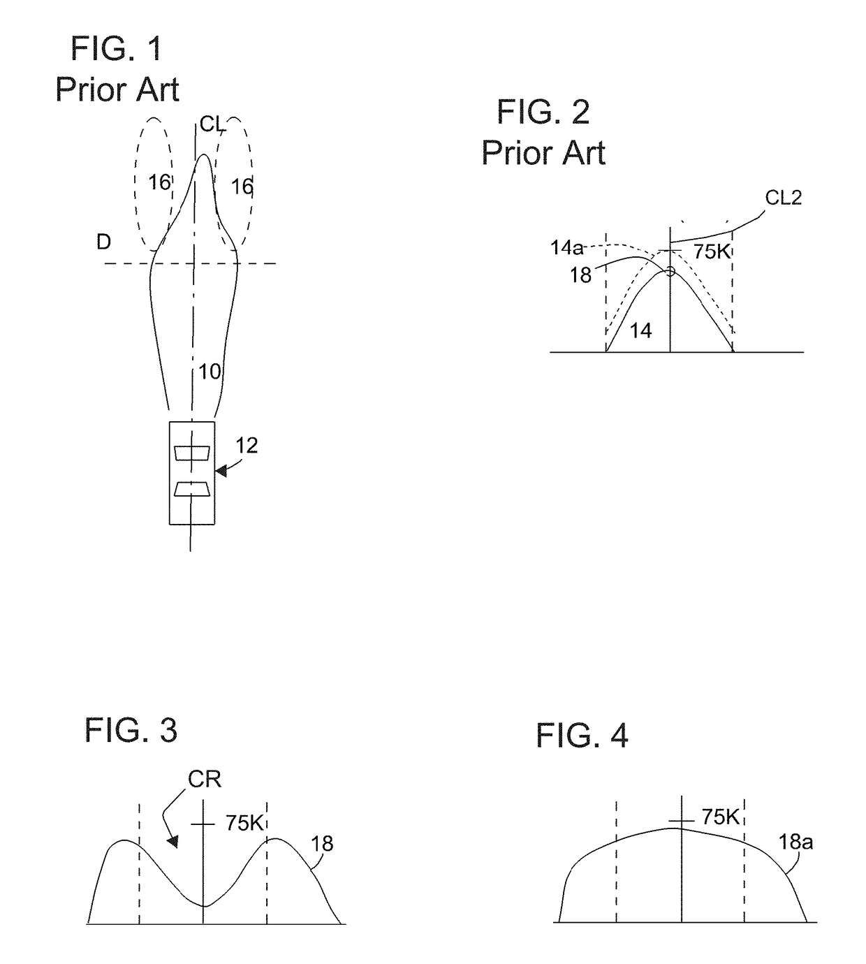
[0097]FIG. 1 is a prior art view that illustrates a simplified pattern 10 of light distribution of a headlight in an ordinary motor vehicle 12. FIG. 2 is a simplified prior art representation of the cross-sectional intensity distribution 14 of the pattern 10, taken along dashed line D in FIG. 1.

[0098]It may be desired to increase the light intensity projected into regions 16 in FIG. 1, which flank the main or primary beam pattern 10. If this is done by increasing the intensity of the headlamps, then the intensity at a point P in FIG. 2 may also increase, which may be undesirable. That is, the increase in intensity may shift the entire intensity curve in FIG. 2 upward to curve 14a shown in phantom. However, government regulations place limits on the maximum intensity allowed on headlamps. The level labeled 75K in FIG. 2 represents such a limit, and the shifted curve 14a would exceed this regulated limit. In FIG. 2, the line labeled 75K represents a limit of intensity, imposed by gove...


PUM


Abstract

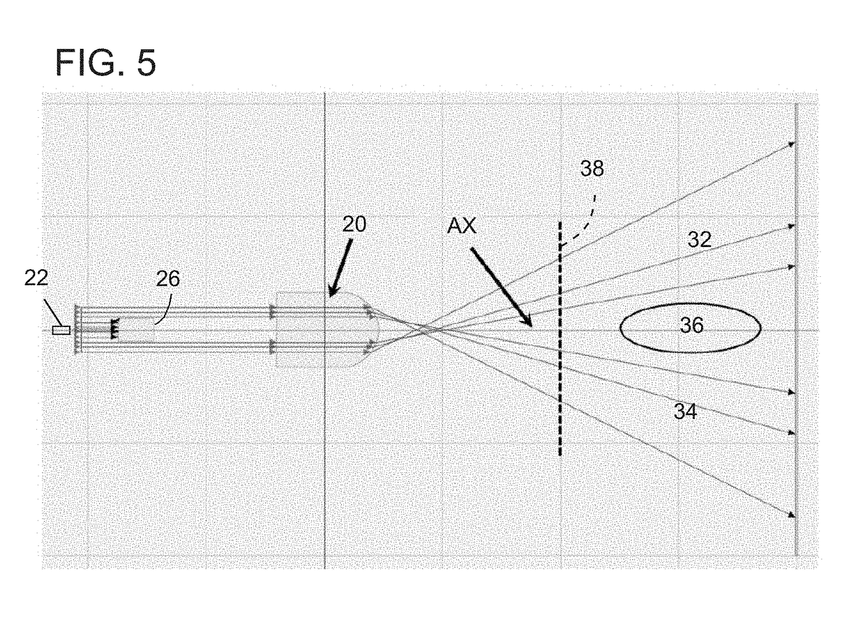
A vehicle lighting system that projects a primary beam and that comprises a supplemental or auxiliary beam that augments the primary beam that does not exceed any regulatory maximum intensity values. In one embodiment, the lighting system utilizes a multi-lobed lens adapted to distribute light to predetermined areas of the primary beam. A combined beam is created having no portion that exceeds the regulatory maximum intensity. In one illustrative embodiment, the primary beam is a high beam and the combined beam is an augmented primary beam that does not exceed the high beam regulatory limit of 75,000 candelas.

Description

BACKGROUND OF THE INVENTION1. Field of the Invention[0001]This invention relates to a lighting device for producing a supplemental beam, particularly, a supplemental high beam.2. Description of the Related Art[0002]In the past, vehicles have been provided with headlamp assemblies that produce multiple beam functions, such as low beam and high beam functions. In some vehicle markets, high beams are limited to a maximum intensity by governmental regulatory authorities. A typical high intensity lighting device for a SAE supplemental high beam market have been designed using high luminous, high output LED, such as a laser LED, and imaging systems. Because the maximum high beam output is limited to, for example, 75,000 candelas, the use of supplemental high beam lamps that add additional light to the high beam is of limited benefit because the combination of a supplemental beam with a high beam cannot exceed the 75,000 candelas limit.[0003]Some prior art lighting systems, such as adaptiv...

Claims


Application Information

Patent Timeline
Patent Type & Authority Applications(United States)
IPC IPC(8): F21S8/10
CPCF21S48/1225F21S48/115F21S41/141G02B27/30F21S41/285B60Q1/18F21S41/143F21S41/255F21S41/27F21S41/663F21W2102/13
Inventor ORISICH, JOHN STEVENPOTTER, BRANT JAMES
Owner VALEO NORTH AMERICA
Learn More