
Headset visual displacement for motion correction

Active Publication Date: 2018-03-15
VERIZON PATENT & LICENSING INC
View PDF14 Cites 29 Cited by
  • Summary
  • Abstract
  • Description
  • Claims
  • Application Information

AI Technical Summary

Benefits of technology

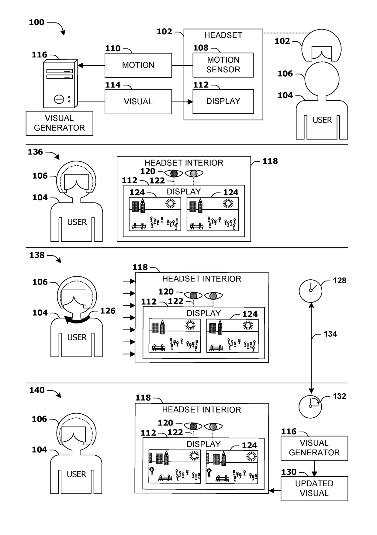
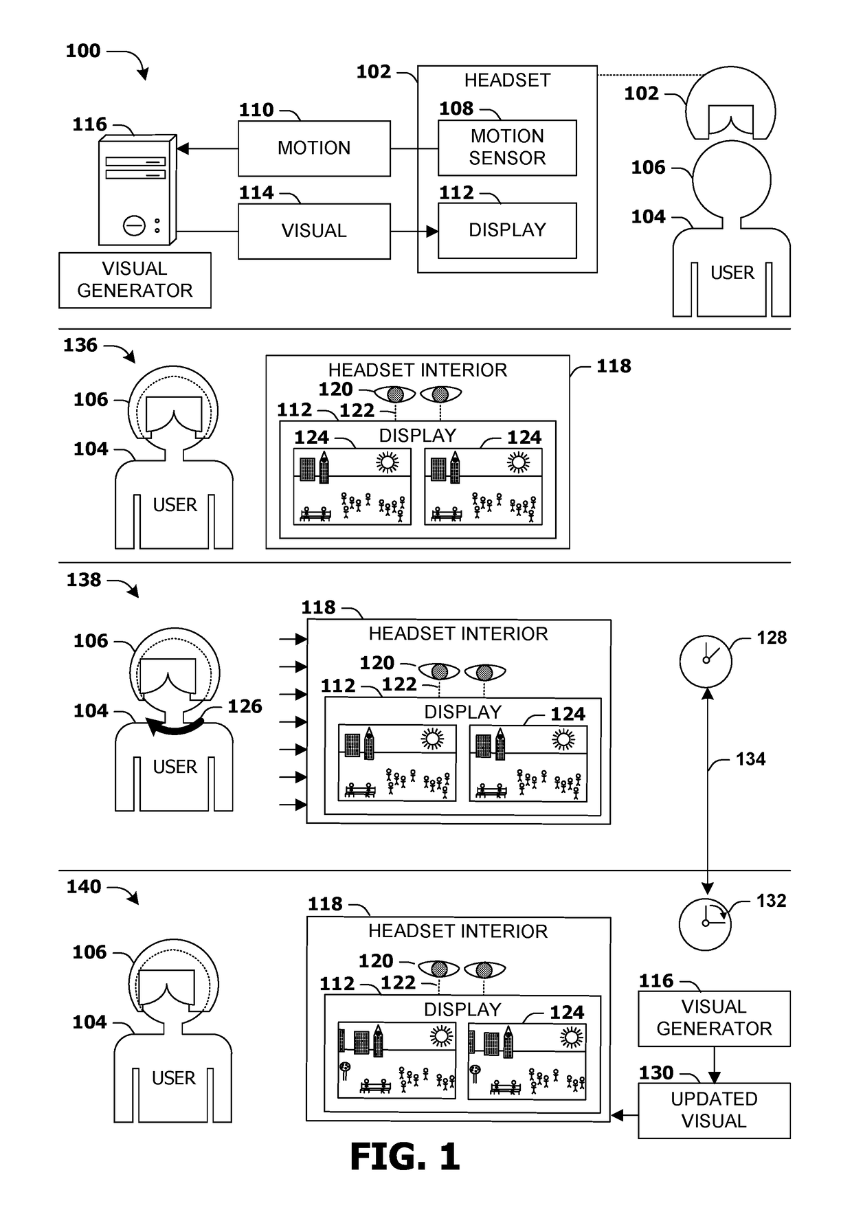
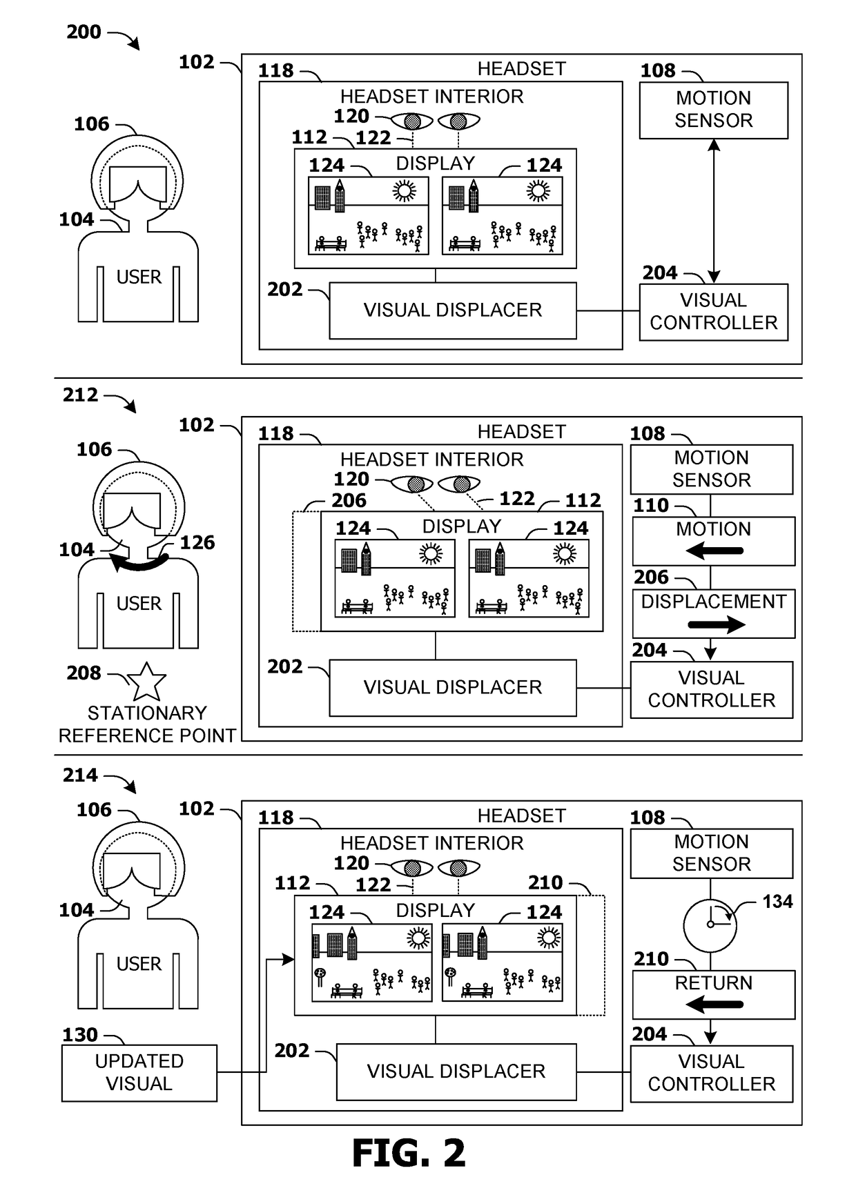
This patent describes a technique for improving the user experience when wearing a headset. By physically moving the display within the headset to match the user's motion, the virtual scene can appear to shift as the user moves their head. This counter-displacement of the display helps alleviate the feeling of being in a stationary position while the visuals update. Physical devices can detect and respond to motion much faster than the rendering engines can produce new visuals, which reduces the feeling of lag and motion sickness. Overall, this technique creates a more immersive experience for users wearing headsets.

Problems solved by technology

For example, a headset may be capable of maintaining a generally consistent framerate of 100 Hz, a perceivable delay in the range of ten milliseconds arises between the user's motion and the corresponding translation within the scene—often longer if the scene renderer misses a frame, or is not capable of incorporating a detected motion into the very next frame.
The user's perception of this delay may give rise to vertigo and / or motion sickness, which may considerably impair the user's enjoyment of using the headset.

Method used


Image

  • Headset visual displacement for motion correction
  • Headset visual displacement for motion correction
  • Headset visual displacement for motion correction

Examples


Embodiment Construction

[0019]Subject matter will now be described more fully hereinafter with reference to the accompanying drawings, which form a part hereof, and which show, by way of illustration, specific example embodiments. This description is not intended as an extensive or detailed discussion of known concepts. Details that are known generally to those of ordinary skill in the relevant art may have been omitted, or may be handled in summary fashion.

[0020]The following subject matter may be embodied in a variety of different forms, such as methods, devices, components, and systems. Accordingly, this subject matter is not intended to be construed as limited to any example embodiments set forth herein; example embodiments are provided merely to be illustrative. Such embodiments may, for example, take the form of hardware, software, firmware or any combination thereof (other than software per se). A reasonably broad scope for claimed or covered subject matter is intended.

1. Motion-Responsive Headsets

[...


PUM


Abstract

Many headset devices, such as virtual reality helmets, present visuals that respond to the user's motion, such that a rotation of the user's head causes the visual to be re-rendered from a correspondingly rotated perspective. The lag between the user's motion and the updated rendering from the new perspective may be perceivable even at high framerates, and may induce unpleasant feelings such as vertigo. Instead, headset devices may respond to detected motion by identifying a displacement of the physical location of the visual that causes it to maintain a physical position relative to a stationary reference point. The display is operatively coupled with a displacer, such as actuators or a projection adjustment, that are engaged to displace the display according to the identified displacement and maintain a physical location of the visual relative to the stationary reference point (e.g., until the visual is re-rendered from the updated perspective).

Description

BACKGROUND[0001]Within the field of computing, many scenarios involve a headset that presents a visual to a user, where the visual is rendered to translate the motion of the user into a corresponding motion of the visual. For instance, a display mounted within a virtual reality helmet may project a three-dimensional rendering of a scene from a particular perspective, where the motion of the user (e.g., tilting or turning the head; ducking or jumping; or stepping forward, backward, left or right) may cause a scene renderer to render the scene from an altered perspective corresponding to the user's motion.[0002]In such scenarios, many users perceive a lag between the motion and the corresponding rendering of the scene. For example, a headset may be capable of maintaining a generally consistent framerate of 100 Hz, a perceivable delay in the range of ten milliseconds arises between the user's motion and the corresponding translation within the scene—often longer if the scene renderer m...

Claims


Application Information

Patent Timeline
IPC IPC(8): G06T19/00G06F3/041G06T7/00G06F3/01
CPCG06T19/006G06F3/012G06T7/004G06F3/041G06F3/011G06F3/0346G06T7/70A01K15/025A63B21/0055A63B43/06A63B69/0053A63B71/0622A63B2071/0602A63B2071/0625A63B2071/063A63B2220/17A63B2220/18A63B2220/40A63B2220/803A63B2220/833A63H5/00A63H29/22A63H29/24A63H33/18A63H33/26G10H1/26G10H2220/395G10H2230/055H02J50/90H02J50/10H02J50/20A63B43/004A63B2220/51A63B2220/53A63B2220/56A63B2220/805A63B2225/54G01P1/07G01P1/08G01P15/18G08B5/36G08B21/182H02J7/0068H02J7/32H02J7/0013A63B2225/74
Inventor SCHILLINGS, BENOIT
Owner VERIZON PATENT & LICENSING INC
Learn More