Method and appratus for encoding a digital video signal

a digital video and signal technology, applied in the field of method and appratus for encoding a digital video signal, can solve the problems of discomfort for a viewer of a 3d video sequence, one does not know exactly how to translate the disparity map of a texture image solely from these gray-level data,

Active Publication Date: 2006-02-02
KONINKLIJKE PHILIPS ELECTRONICS NV
View PDF4 Cites 11 Cited by
  • Summary
  • Abstract
  • Description
  • Claims
  • Application Information

AI Technical Summary

Benefits of technology

[0020] As we will see in detail, by encoding the type of the disparity map, and more precisely by encoding the way to compute the disparity values from the 8 bits of gray le

Problems solved by technology

One inconvenience of these encoding schemes is that, at the receiver side, one does not know exactly how to translate the disparity map of a texture

Method used


Image

  • Method and appratus for encoding a digital video signal

Examples


Embodiment Construction

[0024] In the following description, functions or constructions well known to the person skilled in the art are not described in detail because they would obscure the invention in unnecessary detail.

[0025] The present invention relates to a method for encoding a digital video sequence, said digital video sequence comprising some sets of images, usually one first set of texture images along with another set of images called disparity images or disparity maps. A disparity map is used to reconstruct one image of a set of texture images from a reference image of said set of texture images.

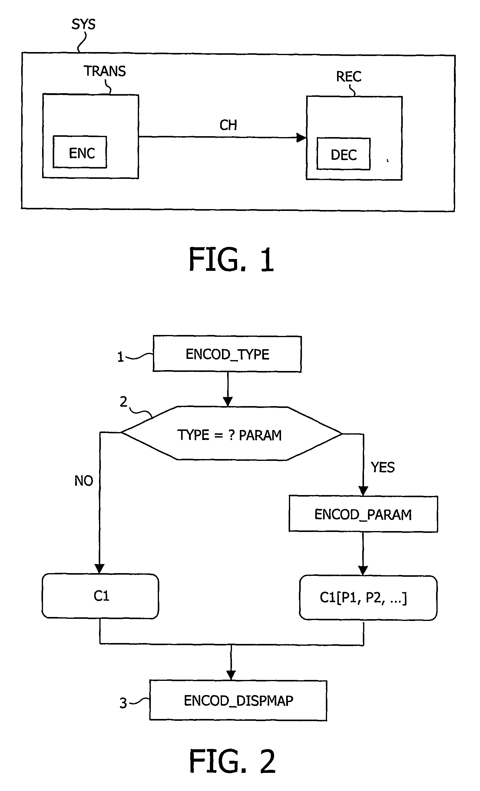
[0026] Such a method may be used within a video communication system SYS for 3D video applications in MPEG2 or MPEG4, wherein said video communication system comprises a transmitter TRANS, a transmission medium CH and a receiver RECEIV. Said transmitter TRANS and said receiver RECEIV comprise an encoder ENC and a decoder DEC, respectively.

[0027] In order to transmit efficiently some video sequences ...


PUM


Abstract

The present invention relates to a method and an encoder for encoding a digital video sequence, said digital video sequence comprising some sets of images including a disparity map, said disparity map being used to reconstruct one image of a set of images from another image of said set of images. The method is characterized in that it comprises the steps of:—encoding a type of a disparity map to be used for the reconstruction of an image, and—encoding the disparity map. Use: encoder in a video communication system

Description

[0001] The present invention relates to a method of encoding a digital video sequence, said digital video sequence comprising some sets of images including disparity maps, a disparity map being used to reconstruct one image of a set of images from a reference image of said set of images. The invention also relates to an encoder, said encoder implementing said method. [0002] Such a method may be used in, for example, a video communication system for 3D video applications within MPEG standards. BACKGROUND OF THE INVENTION [0003] A video communication system typically comprises a transmitter with an encoder and a receiver with a decoder. Such a system receives an input digital video sequence, encodes said sequence via the encoder, transmits the encoded sequence to the receiver, then decodes the transmitted sequence via the decoder, resulting in an output digital video sequence, which is the reconstructed sequence of the input digital video sequence. The receiver then displays said outp...

Claims


Application Information

Patent Timeline
IPC IPC(8): G06K9/36G06K9/46H04N13/239
CPCH04N13/0059H04N13/0239H04N13/0048H04N19/597H04N2013/0081H04N13/194H04N13/161H04N13/239H04N13/00
Inventor AUBERGER, STEPHANEPICARD, YANN
Owner KONINKLIJKE PHILIPS ELECTRONICS NV
Why Eureka
Try Eureka