Circuit board with wire conductive pads and method for fixing the wire conductive pads to the circuit board

a technology of wire conductive pads and circuit boards, which is applied in the direction of sustainable manufacturing/processing, coupling device connections, and final product manufacturing, can solve the problems of unnecessary danger and harm, manual operation of the welding process, etc., and achieve the effect of quick fixing of wires to the circuit boards

Active Publication Date: 2018-03-15
CHIU KAO KUNG +1
View PDF3 Cites 0 Cited by
  • Summary
  • Abstract
  • Description
  • Claims
  • Application Information

AI Technical Summary

Benefits of technology

[0003]One objective of the present invention is to provide a circuit board with wire conductive pads capable of quickly fixing wires to the circuit boards.

Problems solved by technology

Welding process always requires a lot of manual operation.
The solder joints of the circuit boards are large in quantity but micro in size, therefore, workers have to spend a lot of time on welding, and improper welding may cause short circuit between the solder joints or fall off of the wires, etc., resulting in unnecessary danger and harm.

Method used


Image

  • Circuit board with wire conductive pads and method for fixing the wire conductive pads to the circuit board
  • Circuit board with wire conductive pads and method for fixing the wire conductive pads to the circuit board
  • Circuit board with wire conductive pads and method for fixing the wire conductive pads to the circuit board

Examples


Embodiment Construction

[0027]The present invention will be clearer from the following description when viewed together with the accompanying drawings, which show, for purpose of illustrations only, the preferred embodiment in accordance with the present invention.

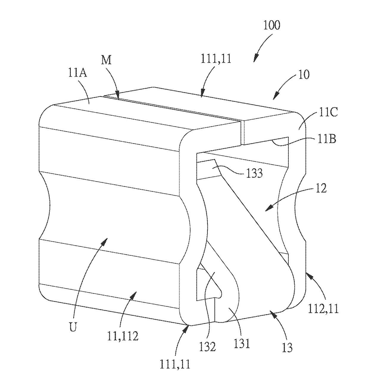
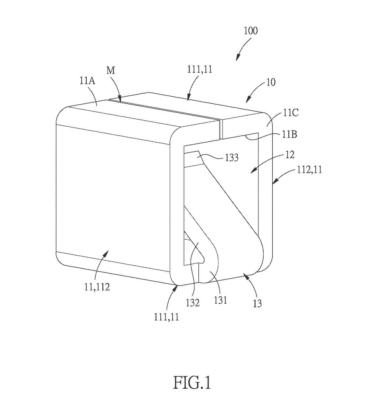
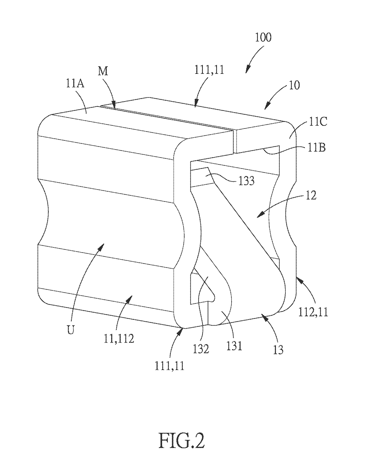
[0028]Referring to FIGS. 1-6, a circuit board with wire conductive pads 100 in accordance with the preferred embodiment of the invention is provided for insertion of a wire L, and includes: a circuit board A and the wire conductive pads 100.

[0029]Each of the wire conductive pads includes a main body 10 and an elastic locking piece 13.

[0030]The circuit board A includes at least one contact point A1.

[0031]The main body 10 is a hollow column made of conductive material, disposed at the contact point A1 of the circuit board A, and includes a peripheral wall 11 which defines an insertion space 12. The peripheral wall 11 includes an outer surface 11A, an opposite inner surface 11B and two lateral surfaces 11C connected between two ends of the outer sur...


PUM


Abstract

A circuit board with wire conductive pads is provided for insertion of wires, and includes: a circuit board and a wire conductive pad. The wire conductive pad includes a main body in the form of a hollow column and an elastic locking piece extending from the main body. The main body includes a peripheral wall defining an insertion space. The elastic locking piece is inserted from the peripheral wall into the insertion space in an inclined manner to press towards the peripheral wall. Wires are inserted into the insertion space and clamped against the peripheral wall by the elastic piece, so that the wires can be prevented from falling off in a reverse direction, and thus can be connected to the circuit board in a more quick and stable manner.

Description

BACKGROUNDField of the Invention[0001]The present invention relates to circuit board peripheral fittings, and more particularly to a circuit board with wire conductive pads, and a method for fixing the wire conductive pads to the circuit board.Related Prior Art[0002]Circuit boards are one of indispensible components to various electronic equipments. When the electronic equipments are different, the configuration and the wiring of the circuit boards therein are also different. Each type of the circuit boards needs to be connected with an input power wire and an output power wire which are usually welded to the circuit boards. Welding process always requires a lot of manual operation. The solder joints of the circuit boards are large in quantity but micro in size, therefore, workers have to spend a lot of time on welding, and improper welding may cause short circuit between the solder joints or fall off of the wires, etc., resulting in unnecessary danger and harm. Hence, there is an u...

Claims


Application Information

Patent Timeline
Patent Type & Authority Applications(United States)
IPC IPC(8): H01R12/72H01R12/75H05K1/11H05K1/18H05K3/34H05K3/22H05K7/06
CPCH01R12/728H01R12/75H05K1/117H05K1/181H05K3/3405H05K3/222H05K7/06H05K2201/10356H05K2201/10446H05K3/32H05K2201/10287H05K2201/1031H05K2201/1034H05K2201/10962Y02P70/50
Inventor CHIU, KAO-KUNGCHENG, SHIN-NUNG
Owner CHIU KAO KUNG
Why Eureka
Try Eureka