
Cross-shaped double sleeve drainage tube

a drainage tube and double sleeve technology, applied in the direction of catheters, intravenous devices, other medical devices, etc., can solve the problems of tissue residual, easy blockage of the drain hole at the bottom end of the negative pressure drainage tube, and affecting the healing of the wound surface of the surgical operation, etc., to achieve efficient facilitating the surgical operation of the doctor

Inactive Publication Date: 2018-03-22
GUANGZHOU SUN SHING BIOTECH CO LTD
View PDF7 Cites 22 Cited by
  • Summary
  • Abstract
  • Description
  • Claims
  • Application Information

AI Technical Summary

Benefits of technology

The present invention is a double sleeve drainage tube that can prevent blockages and monitor the negative pressure of a wound. It includes an inner draining tube, an external sleeve tube, and a connecting member. The tube has multiple draining grooves on its external surface to ensure proper drainage of waste fluid. It also has an infusing tunnel for delivering cleansing fluid or disinfectant to the wound without the need for an additional tube. The technical effect of this invention is to prevent damage to the body caused by uncontrolled negative pressure and facilitate surgical operations.

Problems solved by technology

If the fluid and slough fragments are not immediately removed, the healing of the wound surface of the surgical operation will be affected, and further degeneration of the wound surface might occur in a worse case.
During the draining process, the draining hole at the bottom end of the negative pressure draining tube is easily blocked by tissue residual.
As a result, the negative pressure draining tube is unable to work properly, thereby affecting the normal execution of the surgical operation.

Method used


Image

  • Cross-shaped double sleeve drainage tube
  • Cross-shaped double sleeve drainage tube
  • Cross-shaped double sleeve drainage tube

Examples


Embodiment Construction

[0024]The present invention is explained in conjunction with the accompanying drawings as following, wherein the direction referred in the present invention is defined based on FIG. 1.

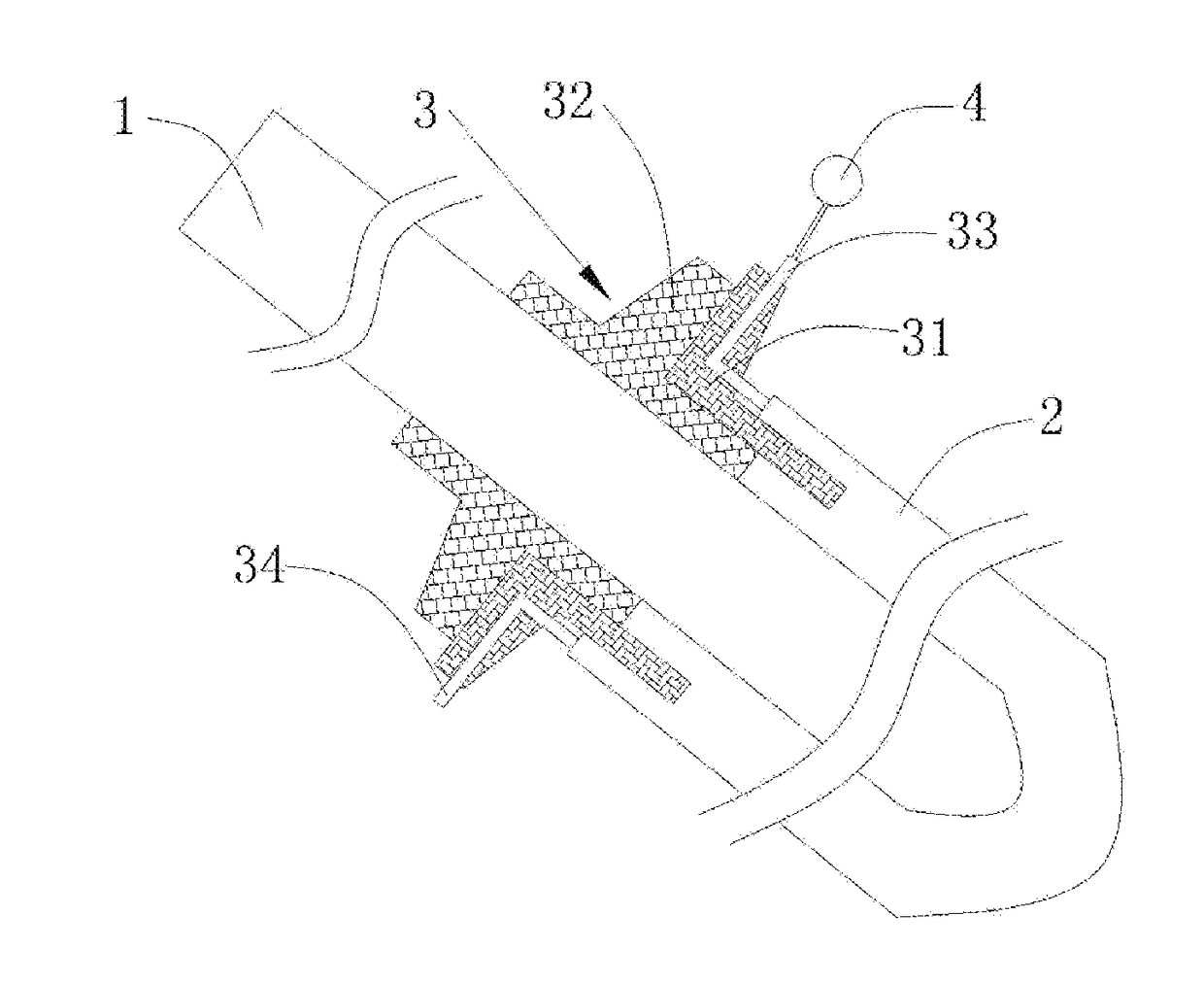
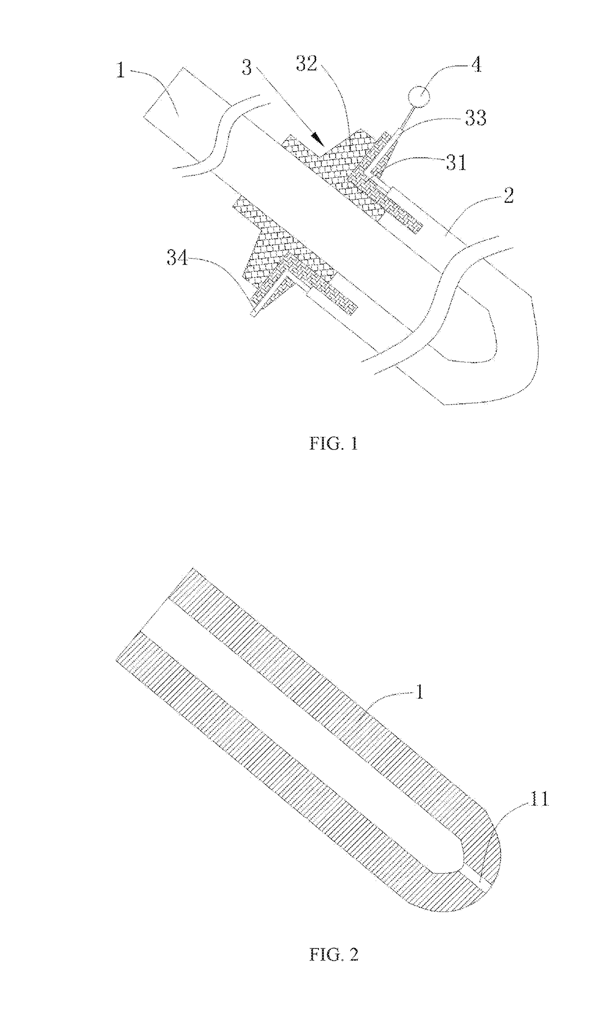
[0025]Referring to FIG. 1, a cross-shaped double sleeve drainage tube in accordance with the present invention comprises an inner draining tube 1, an external sleeve tube 2, a connecting member 3, and a pressure sensor 4. One end of the inner draining tube 1 is connected with an external negative pressure source, and the other end thereof is inserted into the tunnel of the external sleeve tube 2, so as to drain the waste fluid at the location of the wound surface of the surgical operation by use of the negative pressure. The external sleeve tube 2 is applied for preventing the membrane tissues or larger slough tissues in the body from blocking the inner draining tube 1. The connecting member 3 is applied for combining the inner draining tube 1 in the tunnel of the external sleeve tube 2. The pressure s...


PUM


Abstract

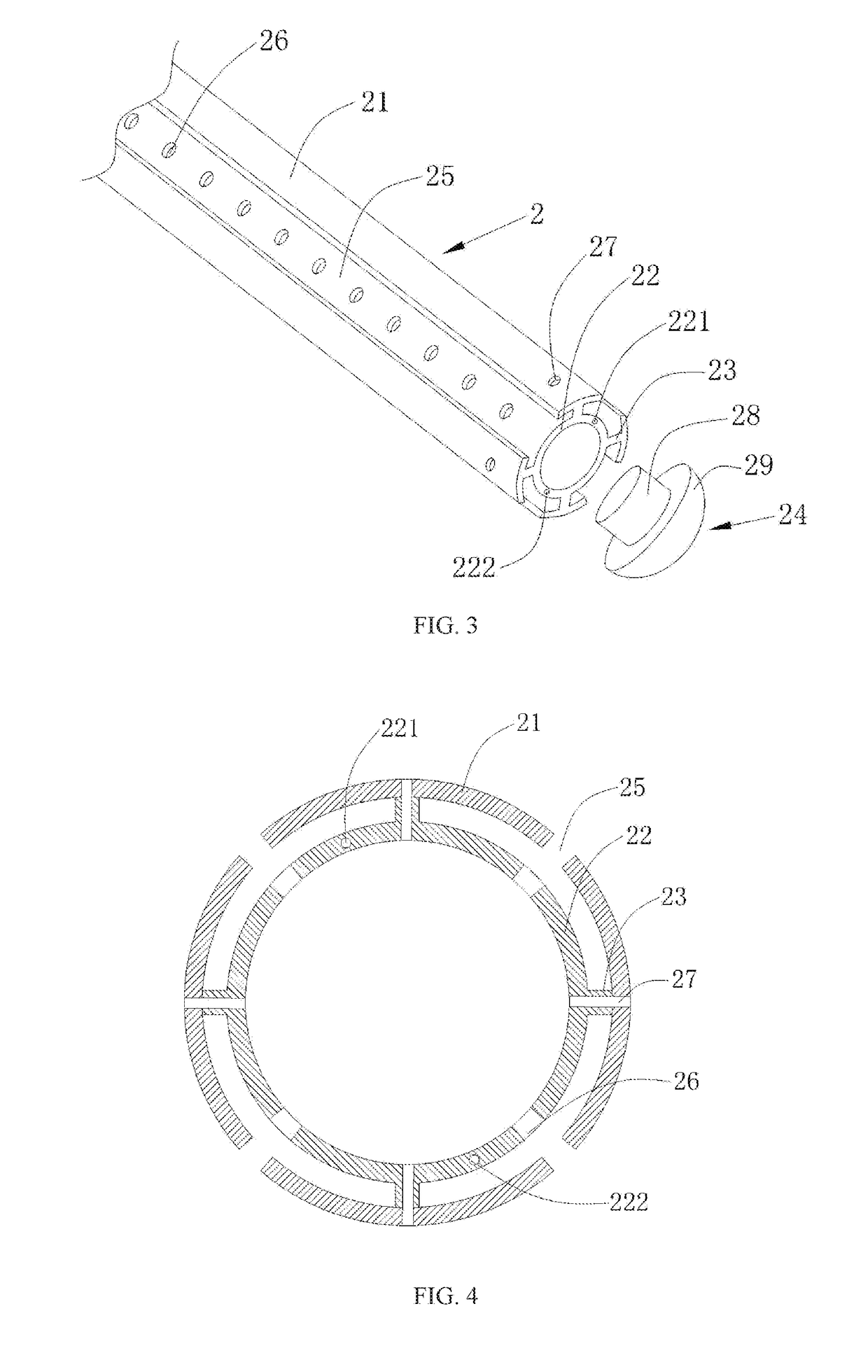
The present invention discloses a cross-shaped double sleeve drainage tube, including an inner draining tube, a connecting member, an external sleeve tube, an inner guiding tube, a support rack, a block member, and a pressure sensor. A left end of the inner draining tube is formed in an opening, and a right end of the inner draining tube is sealed. A tube wall at the right end of the inner draining tube is provided with an inner draining hole. The connecting member combines the inner draining tube in the tunnel of the inner guiding tube. The left and right ends of the external guiding tube are formed in an opening, respectively. The tube wall at the right end of the external guiding tube is provided with a plurality of draining grooves. The inner guiding tube is installed in the tunnel of the external guiding tube through the support rack. The left and right ends of the inner guiding tube are formed in an opening, respectively, with the left end thereof connected with the tube wall of the external guiding tube. The tube wall of the inner guiding tube is provided with a pressure monitoring tunnel, an infusing tunnel, and an external draining hole. The block member includes a block head disposed in the right end opening of the inner guiding tube to block the opening and a block body to block the right end of the external guiding tube. A gap is formed between the left face of the block body and the right face of the external guiding tube. The pressure sensor is connected to the pressure monitoring tunnel.

Description

BACKGROUND OF THE INVENTION1. Field of the Invention[0001]The present invention relates to negative pressure drainage tubes, and more particularly, to a cross-shaped double sleeve drainage tube, which effectively prevents the draining holes from being blocked and monitors the instantaneous negative pressure strength of the wound surface, so as to prevent the tissue and organs in the body from being damaged due to an overpowered negative pressure.2. Description of the Related Art[0002]During a surgical operation treatment, blood, pus, tissue fluid, and excretion possibly accumulate at the lesion or wound. If the fluid and slough fragments are not immediately removed, the healing of the wound surface of the surgical operation will be affected, and further degeneration of the wound surface might occur in a worse case. Presently effectively solution applies a negative pressure draining technique to discharge the fluid and slough fragments. During the surgical operation, a negative press...

Claims


Application Information

Patent Timeline
Patent Type & Authority Applications(United States)
IPC IPC(8): A61M1/00
CPCA61M1/008A61M1/0086A61M1/0084A61M2205/3344A61M25/0043A61M2025/006A61M25/0662A61M27/00A61M1/86A61M1/84
Inventor PENG, YUNYANG, XI FENGZENG, CHEN GUANG
Owner GUANGZHOU SUN SHING BIOTECH CO LTD
Learn More