Digital Printing Process

a digital printing and digital printing technology, applied in the direction of printing, duplicating/marking methods, ink transfer from master sheets, etc., can solve the problems of unsuitable printing applications, limited resolution of such processes, and inability to produce photographic quality acceptable for publications, etc., to achieve uniform color, high resolution, and high quality

Active Publication Date: 2018-03-22
LANDA
View PDF3 Cites 22 Cited by
  • Summary
  • Abstract
  • Description
  • Claims
  • Application Information

AI Technical Summary

Problems solved by technology

Color laser printers using dry toners are suitable for certain applications, but they do not produce images of a photographic quality acceptable for publications, such as magazines.
In general, the resolution of such processes is limited due to wicking by the inks into paper substrates.
Using specially coated substrates is, however, a costly option that is unsuitable for certain printing applications, especially for commercial printing.
Furthermore, the use of coated substrates creates its own problems in that the surface of the substrate remains wet and additional costly and time consuming steps are needed to dry the ink, so that it is not later smeared as the substrate is being handled, for example stacked or wound into a roll.
Furthermore, excessive wetting of the substrate causes cockling and makes printing on both sides of the substrate (also termed perfecting or duplex printing) difficult, if not impossible.
Furthermore, inkjet printing directly onto porous paper, or other fibrous material, results in poor image quality because of variation of the distance between the print head and the surface of the substrate.
However, silicone is hydrophobic which causes the ink droplets to bead on the transfer member.
This makes it more difficult to remove the water in the ink and also results in a small contact area between the droplet and the blanket that renders the ink image unstable during rapid movement.
While these do help to alleviate the problem partially, they do not solve it.

Method used


Image

  • Digital Printing Process
  • Digital Printing Process
  • Digital Printing Process

Examples


Embodiment Construction

General Overview

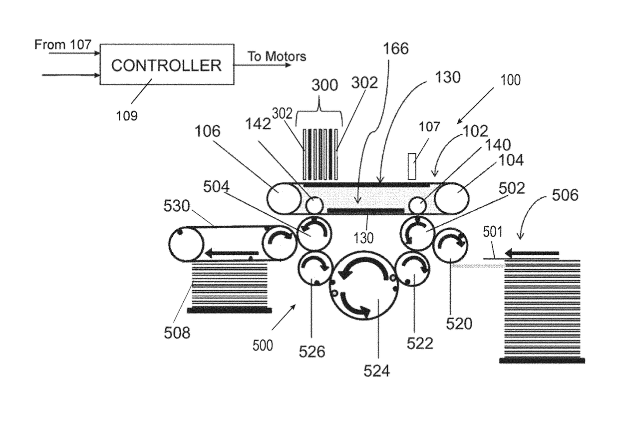
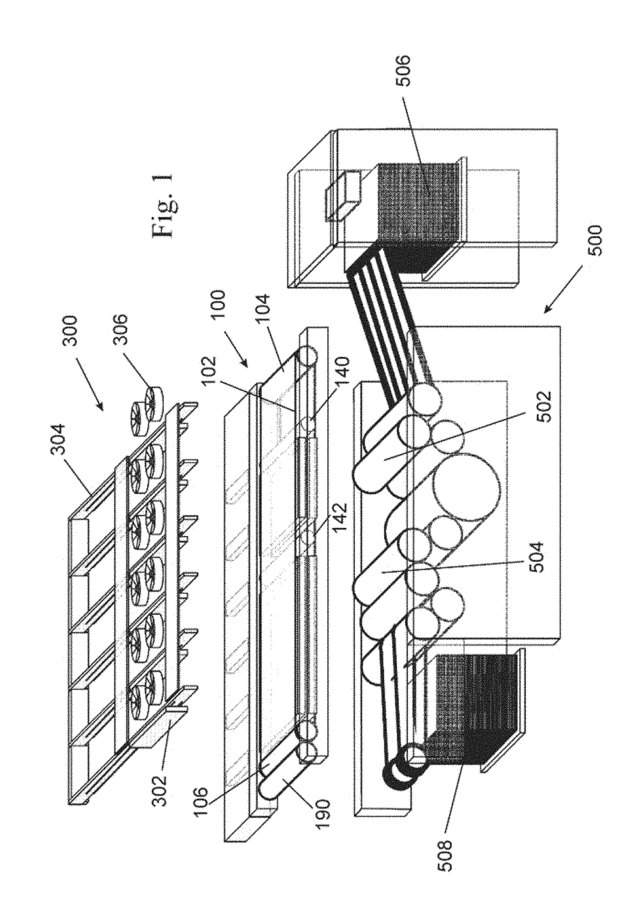
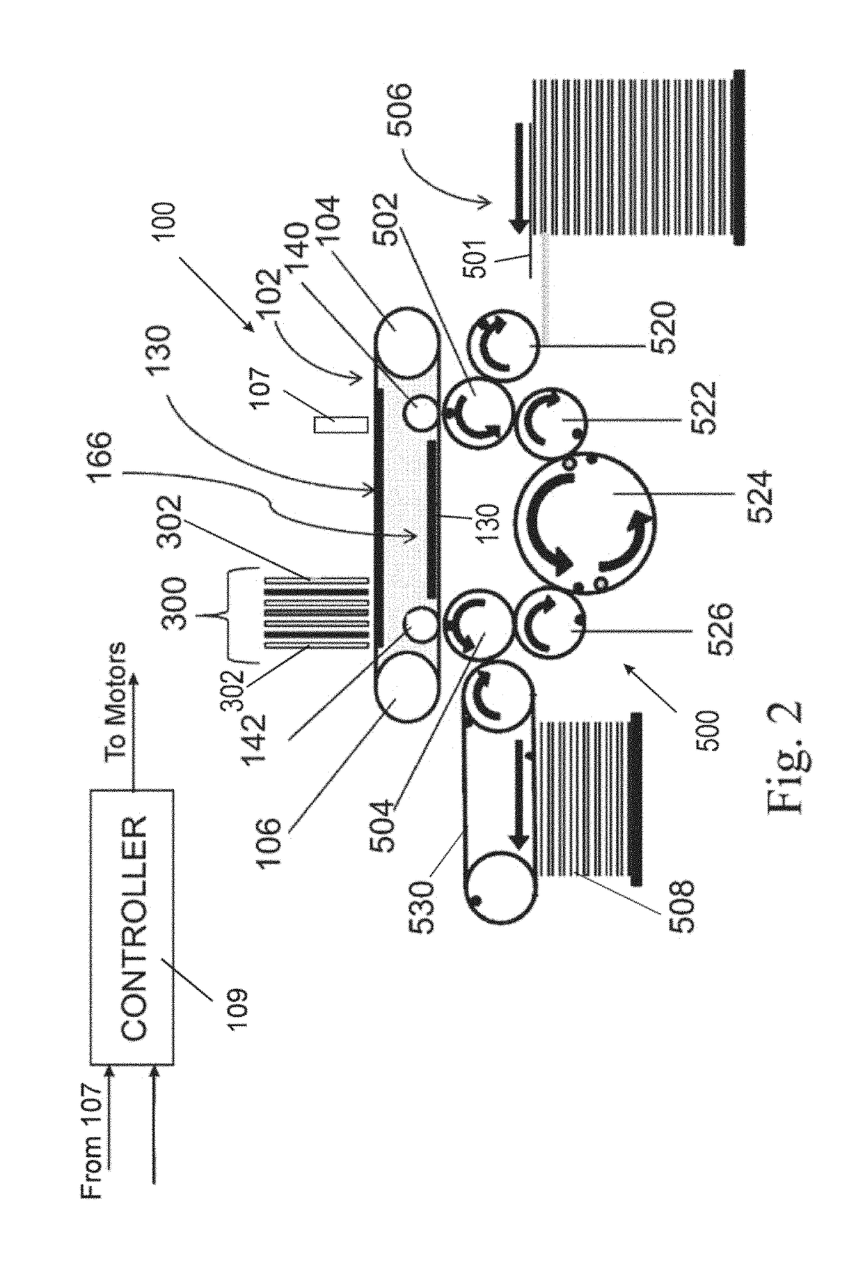
[0029]In addition, the present disclosure describes a printing process which includes directing droplets of an ink onto an intermediate transfer member to form an ink image, the ink including an organic polymeric resin and a coloring agent in an aqueous carrier, and the transfer member having a hydrophobic outer surface, each ink droplet in the ink image spreading or impinging upon the intermediate transfer member to form an ink film; drying the ink while the ink image is being transported by the intermediate transfer member by evaporating the aqueous carrier from the ink image to leave a residue film of resin and coloring agent; and transferring the residue film to a substrate, wherein the chemical compositions of the ink and of the surface of the intermediate transfer member are selected such that attractive intermolecular forces between molecules in the outer skin of each droplet and on the surface of the intermediate transfer member counteract the tendency of the...


PUM

PropertyMeasurementUnit
lengthaaaaaaaaaa
speedaaaaaaaaaa
speedaaaaaaaaaa

Abstract

A printing system is disclosed which includes a plurality of rollers configured to support and move a loop-shaped, flexible intermediate transfer member of at least 10 meters in length along a printing system path. The printing system further includes an image forming station configured to form an image on a portion of the intermediate transfer member, and an impression station configured to enable substantial transfer of the deposited image to a substrate. The printing system also includes at least one high-speed motor associated with the plurality of rollers and configured to move the loop-shaped flexible intermediate transfer member at a speed of at least about one meter per second. Moreover, the printing system includes guiding channels configured for exerting a lateral tensioning force on the loop-shaped intermediate transfer member as it is received within the guiding channels and circulates at the speed of at least about one meter per second.

Description

CROSS-REFERENCE TO RELATED APPLICATIONS[0001]This application is a continuation-in-part of U.S. patent application Ser. No. 15 / 674,811, filed on Aug. 11, 2017 which is a continuation-in-part of and claims priority from U.S. patent application Ser. No. 15 / 175,275, filed Jun. 7, 2016 (now U.S. Pat. No. 9,776,391), which is a continuation of U.S. patent application Ser. No. 14 / 382,751, filed on Sep. 3, 2014 (now U.S. Pat. No. 9,381,736), which is a U.S. national application of PCT International Application No. PCT / IB2013 / 051716, filed Mar. 5, 2013, that claims the benefit of the following U.S. provisional Applications: U.S. Provisional Patent Application No. 61 / 640,642, filed Apr. 30, 2012; U.S. Provisional Patent Application No. 61 / 640,637, filed Apr. 30, 2012; U.S. Provisional Patent Application No. 61 / 640,493, filed Apr. 30, 2012; U.S. Provisional Patent Application No. 61 / 637,301, filed Apr. 24, 2012; U.S. Provisional Patent Application No. 61 / 635,156, filed Apr. 18, 2012; U.S. Pro...

Claims


Application Information

Patent Timeline
Patent Type & Authority Applications(United States)
IPC IPC(8): B41J2/005B41M5/025B41M5/03B41N10/00
CPCB41N10/00B41J2/0057B41M5/0256B41M5/03
Inventor LANDA, BENZIONSHEINMAN, YEHOSHUAABRAMOVICH, SAGIGOLODETZ, GALIANAKHMANOVICH, GREGORYSORIA, MEIR
Owner LANDA
Why Eureka
Try Eureka