Structure and method of making the same

a technology of structure and method, applied in the field of structures, can solve the problems of preventing such buildings/structures from achieving substantial height, and preventing the advancement of modern building design

Inactive Publication Date: 2018-03-22
SKYRISE GLOBAL LLC
View PDF3 Cites 0 Cited by
  • Summary
  • Abstract
  • Description
  • Claims
  • Application Information

AI Technical Summary

Benefits of technology

[0013]One or more of the following features may be included. The floor tying assembly may be configured to index the plurality of floor plate assemblies with respect to each other and transfer the load of the plurality of floor plate assemblies to the truss assembly. At least one of the plurality of floor plate assemblies positioned toward the top of the entertainment structure may be larger than at least one of the plurality of floor plate assemblies positioned toward the bottom of the entertainment structure.
[0014]The details of one or more implementations are set forth in the accompanying drawings and the description below. Other features and advantages will become apparent from the description, the drawings, and the claims.

Problems solved by technology

For example, prior to the use of structural steel within buildings / structures, buildings / structures were constructed out of some form of stone, which prevented such buildings / structures from achieving substantial height, as the lower walls of the building / structure would need to be prohibitively thick in order to bear the weight of the upper portion of the building / structure.
However, as the design of buildings / structures changed and advanced throughout the years, buildings / structures unimaginable at one time are now highly achievable.
Unfortunately, the continued use of such traditional building techniques often prevents the advancement of modern building design.

Method used


Image

  • Structure and method of making the same
  • Structure and method of making the same
  • Structure and method of making the same

Examples


Embodiment Construction

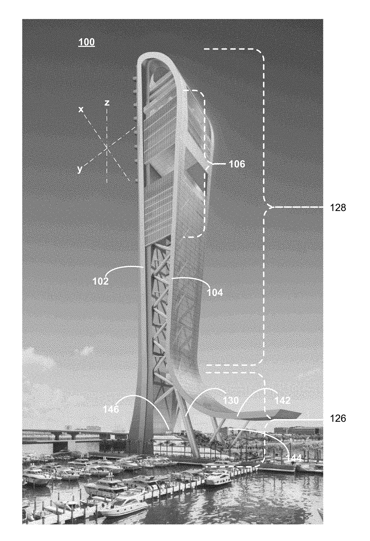
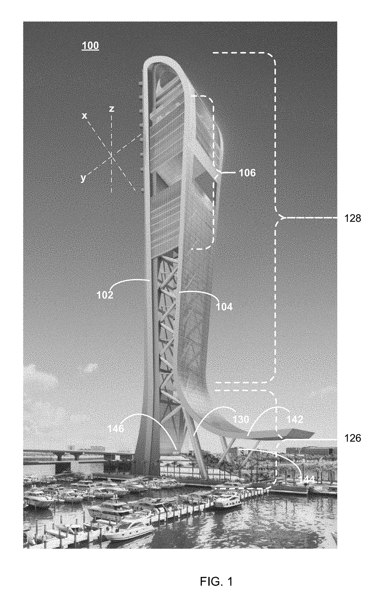
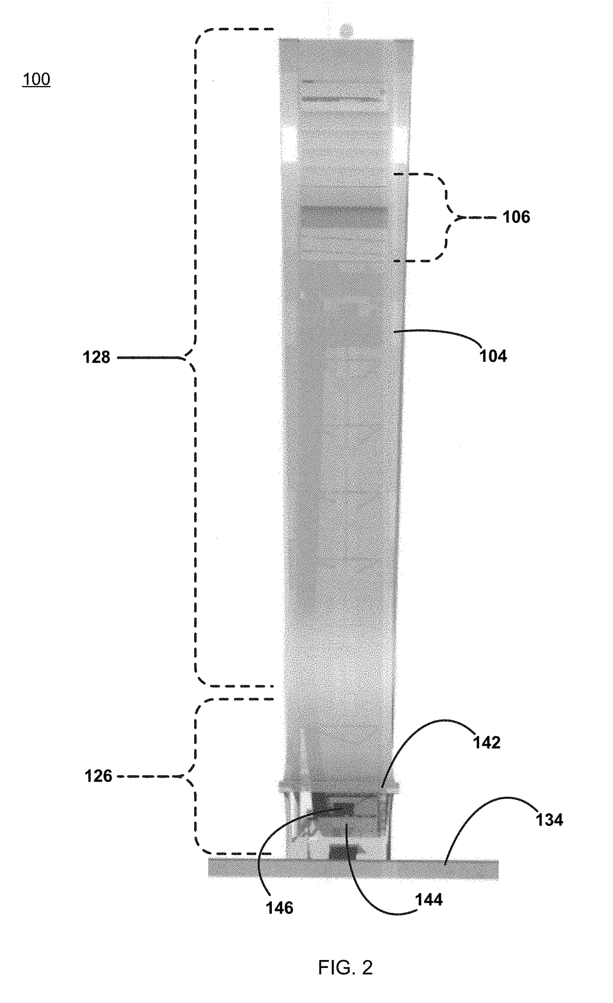
[0031]Referring to FIGS. 1-5, there is shown various views of structure 100. Specifically, FIG. 1 is a perspective view of structure 100, FIG. 2 is a front view of structure 100, FIG. 3 is a right-side view of structure 100, FIG. 4 is a left-side view of structure 100, and FIG. 5 is a back view of structure 100. Examples of structure 100 may include but is not limited to a residential building / structure, a office building / structure, a vertical entertainment building / structure, a tower structure, and an observation structure. Structure 100 may include offset core 102, moment stabilizing structure 104 and plurality of floor plate assemblies 106.

[0032]Offset core 102 may be a concrete offset core, wherein this concrete offset core may be a slip-formed concrete offset core. As is known in the art, slip forming (also known as continuous pouring and / or continuous forming) is a construction method in which concrete is poured into a continuously moving form.

[0033]Slip forming may be used fo...


PUM


Abstract

An entertainment structure includes: an offset core; a moment stabilizing structure configured to span an entryway; and a canopy assembly coupled to the moment stabilizing structure and configured to form an atrium proximate the entryway.

Description

RELATED APPLICATION(S)[0001]This application claims the benefit of U.S. Provisional Application No. 62 / 397,681, filed on 21 Sep. 2016; the contents of which are incorporated herein by reference.TECHNICAL FIELD[0002]This disclosure relates to structures and, more particularly, to entertainment structures and methods of making the same.BACKGROUND[0003]Throughout the years, the manner in which buildings and structures have been constructed has greatly changed. For example, prior to the use of structural steel within buildings / structures, buildings / structures were constructed out of some form of stone, which prevented such buildings / structures from achieving substantial height, as the lower walls of the building / structure would need to be prohibitively thick in order to bear the weight of the upper portion of the building / structure.[0004]However, as the design of buildings / structures changed and advanced throughout the years, buildings / structures unimaginable at one time are now highly ...

Claims


Application Information

Patent Timeline
Patent Type & Authority Applications(United States)
IPC IPC(8): E04B1/343
CPCE04B1/343B66B9/00E04B1/20E04B1/2403E04B1/30E04B2001/2484A63G31/00A63G2031/002E04H3/00A63G31/10E04B1/3522E04B2001/3588A63G21/04E04B1/16E04B1/19E04B1/3511A63G7/00E04B1/161E04B1/24E04B1/34823E04B2103/02E04B2103/06
Inventor BERKOWITZ, JEFFREYFORT-BRESCIA, BERNARDOKLEMENCIC, RONALD
Owner SKYRISE GLOBAL LLC
Why Eureka
Try Eureka