Combustor front assembly for a gas turbine

a technology for gas turbines and components, applied in continuous combustion chambers, combustion processes, lighting and heating apparatus, etc., can solve the problems of high vibration, frequent failure of the foregoing described hook fixing system solution of the prior art, etc., and achieve the effect of increasing the lifetime and the reliability of the fixation

Inactive Publication Date: 2018-03-22
ANSALDO ENERGIA IP UK LTD
View PDF1 Cites 0 Cited by
  • Summary
  • Abstract
  • Description
  • Claims
  • Application Information

AI Technical Summary

Benefits of technology

[0013]Accordingly, a primary object of the present invention is to provide a combustor front assembly for a gas turbine that allows to incr

Problems solved by technology

However, the combustor front segment 22 are exposed to high level of vibrations and thermal deformation and, unfortunately, the foregoing described hook fixing system

Method used


Image

  • Combustor front assembly for a gas turbine
  • Combustor front assembly for a gas turbine
  • Combustor front assembly for a gas turbine

Examples


Embodiment Construction

[0056]In cooperation with attached drawings, the technical content and the detailed description of the present invention are described thereinafter according to preferable embodiments, being not used to limit its executing scope. Any equivalent variation and modification made according to appended claims is all covered by the claims claimed by the present invention.

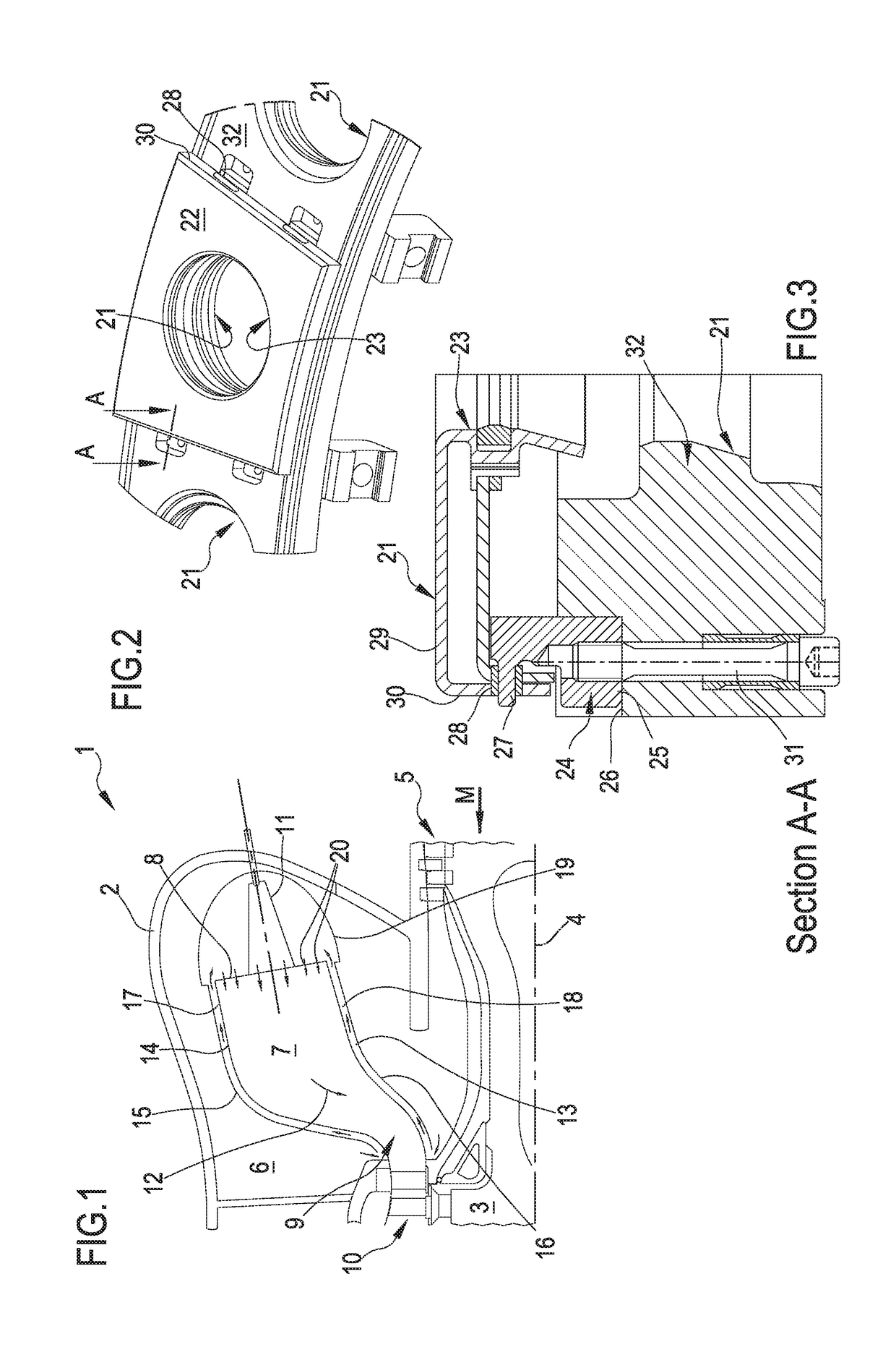
[0057]In particular, reference will be made to the FIGS. 4-11 that disclose in detail an embodiment of the present invention. Reference to FIG. 1, that is a schematic view of a gas turbine, will be made only in order to explain how the invention cooperates with the relative gas turbine.

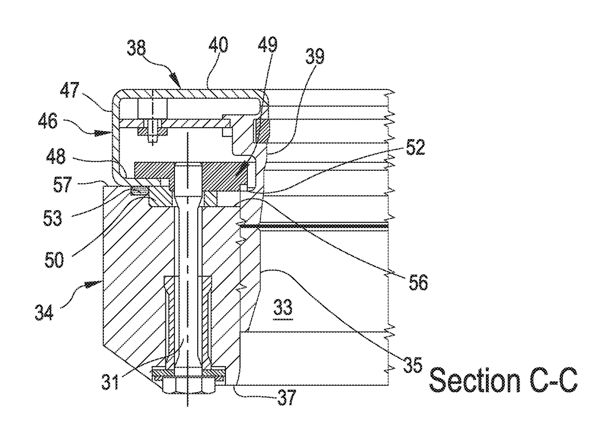
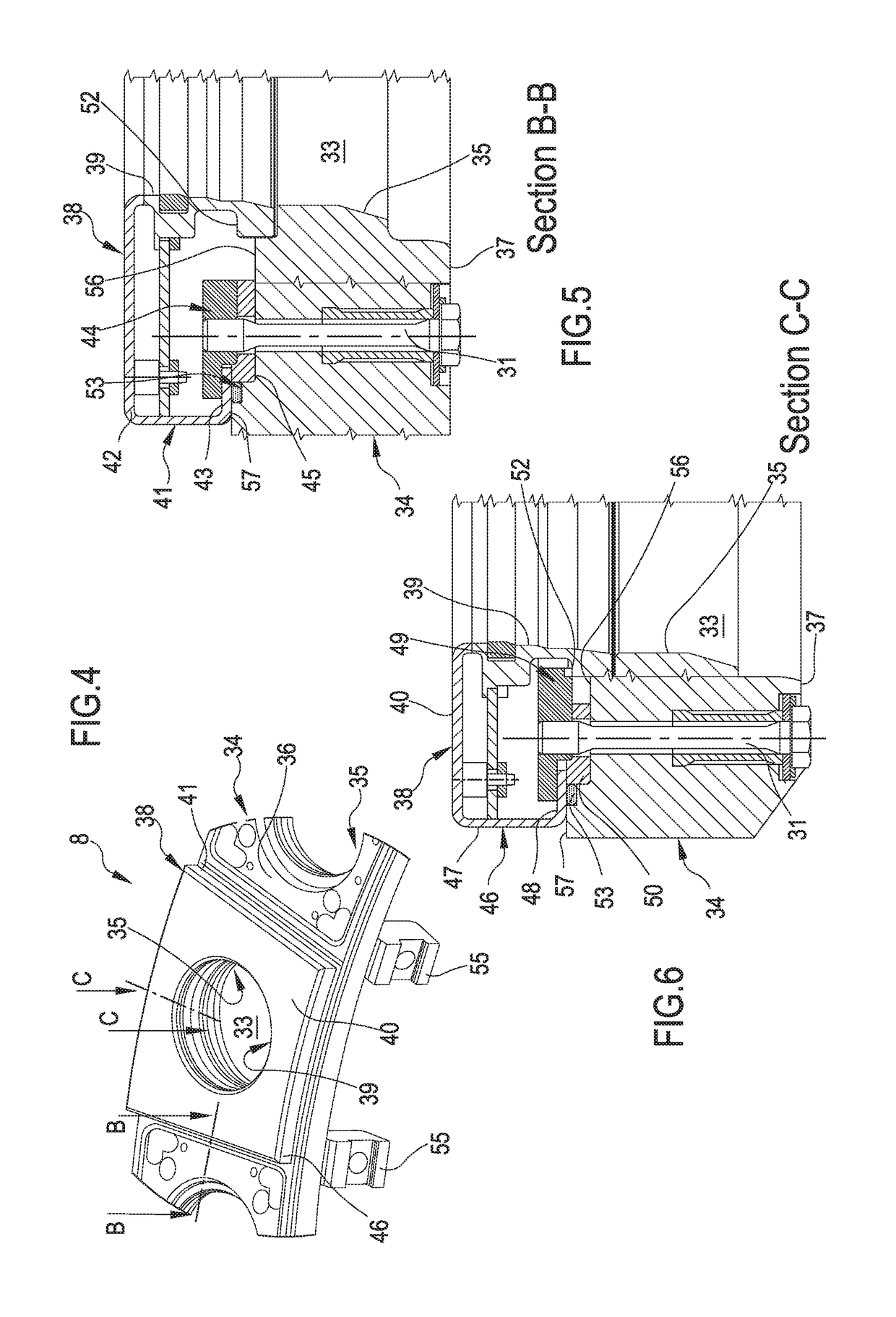
[0058]Reference in now made to the FIG. 4 that is a schematic partial prospective view of a front combustor assembly, on the burner side, according to the invention.

[0059]In particular, the FIG. 4 discloses a portion of a ring-shaped combustor front plate 34 centered around the turbine axis 4 (see also FIG. 1) and a tile-shaped combustor fr...


PUM


Abstract

A combustor front assembly for a gas turbine power plant, wherein the combustor front assembly is provided with at least a through hole for allowing gas flow into a combustion chamber, the combustor front assembly having a combustor front plate with at least a through hole and with an outer surface outside the combustor chamber; a combustor front segment having a through hole and coupled with the outer surface of the combustor front plate so that the through hole of the front segment is aligned with the through hole of the front plate; wherein the combustor front segment is clamped in position and forced against the outer surface of the combustor front plate.

Description

PRIORITY CLAIM[0001]This application claims priority from European Patent Application No. 16190197.0 filed on Sep. 22, 2016, the disclosure of which is incorporated by reference.FIELD OF THE INVENTION[0002]The present invention relates to a combustor front assembly for a gas turbine power plant.[0003]In particular, the present invention refers to an annular combustor front assembly suitable to be preferably associated with a plurality of EV burners.[0004]Moreover, the present invention refers to a gas turbine power plant provided with the above combustor front assembly.DESCRIPTION OF PRIOR ART[0005]A gas turbine power plant (in the following only gas turbine) comprises, following the main gas flow, a compressor fed with air, one or more combustors fed with the compressed air wherein a fuel is injected, mixed to the air flow and burnt in order to generate an high pressure gas, and a turbine fed with the high pressure gas.[0006]In the case of the gas turbine is provided with an annula...

Claims


Application Information

Patent Timeline
IPC IPC(8): F23R3/04F23R3/00F23R3/60
CPCF23R3/04F23R3/002F23R3/60F23C7/00F23R3/52F23R3/007F23R3/10F23R3/283F23R2900/00012F23R2900/00017
Inventor BEG, MARIJANBENZ, URSCVITAK, BRANKOBELINA, IVOSIEWERT, PIOTR
Owner ANSALDO ENERGIA IP UK LTD
Why Eureka
Try Eureka