
Tensiometer apparatus and method

a technology of tensiometer and apparatus, which is applied in the direction of instruments, fluid pressure measurement, and using mechanical means, can solve the problems of limited water supply to farms, cities, ecosystems, and water shortages, and reduce the use of irrigation for homes and office complexes, and reduce the use of irrigation

Active Publication Date: 2018-03-22
LAFIAN JESSE
View PDF0 Cites 16 Cited by
  • Summary
  • Abstract
  • Description
  • Claims
  • Application Information

AI Technical Summary

Benefits of technology

The invention is a sensor that can measure the pressure inside a hydrogel chamber and convert it to a measurement of soil water content (SWT). This information can be used to make informed decisions about soil irrigation. The sensor sends a signal to a microcontroller, which converts the signal to a determined SWT value at a specific soil depth. This value is displayed on a screen or can be sent to a remote transmission module. Overall, this technology provides a way to monitor soil moisture levels in real-time and make more efficient irrigation decisions.

Problems solved by technology

As global temperatures increase, drought limits the water supply to farms, cities, industries, and ecosystems.
Over-irrigation can contribute to water shortages, plant / crop loss, and pollution caused by agro-chemical runoff.
There are different types of instruments used to measure SWT; however, such instruments have drawbacks that constrict usage for irrigation purposes for homes and office complexes and for farming or other large area irrigation monitoring and control.
A primary drawback arises from the high expense of current options.

Method used


Image

  • Tensiometer apparatus and method
  • Tensiometer apparatus and method
  • Tensiometer apparatus and method

Examples


first embodiment

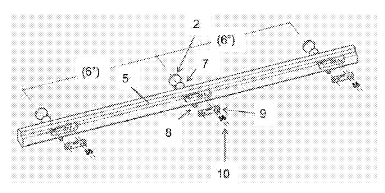
[0062]the elongated probe (illustrated in FIGS. 3-8), uses a load cell 9 as a sensor. The tensiometer of this embodiment comprises a load cell 9 (attached to an inner frame 5 by a pair of screws 10), a dowel pin 8, a flexible barrier 7, a hydrogel chamber 3, hydrogel 15, and a window 2.

[0063]As illustrated in FIG. 6B, the inner frame 5 of the elongated probe defines a hydrogel chamber 3 with an open side 24 and the inner wall 25 that opens to a passageway 26. The hydrogel chamber 3 receives a flexible barrier 7, having one side that is attached to the inner wall 25 with adhesive. The hydrogel chamber 3 receives the hydrogel 15. The passageway 26 receives the dowel pin 8. The dowel pin 8 is movable longitudinally through the passageway 26. A pair of screws 10 secures the load cell 9 to the inner frame 5. An end of the dowel pin 8 contacts the load cell 9. The opposite end of the dowel pin 8 contacts a flexible barrier 7. The flexible barrier 7 retains the hydrogel within the hydrogel...

second embodiment

[0066]the elongated probe (illustrated in FIG. 10 in a side cross-sectional format), uses a linear variable differential transformer (LVDT) 12 as a sensor. The tensiometer of this embodiment comprises an LVDT 12 (attached to an inner frame 5 by adhesive), a flexible barrier 7, a hydrogel chamber 3, hydrogel 15, and a window 2.

[0067]This second embodiment, like the first embodiment, has an inner and outer frame as illustrated in FIG. 6B; the inner frame 5 of the elongated probe defines a hydrogel chamber 3 with an open side 24 and the inner wall 25 that opens to a passageway 26. The hydrogel chamber 3 receives a flexible barrier 7, having one side that is attached to the inner wall 25 with adhesive. The hydrogel chamber 3 receives the hydrogel 15. A portion of the side of the flexible barrier 7 that is movable longitudinally through the passageway 26 contacts the LVDT 12. The flexible barrier 7 retains the hydrogel within the hydrogel chamber 3.

[0068]A durable, hydrophilic, and porou...

third embodiment

[0070]the elongated probe (illustrated in FIG. 11 in a side cross-sectional format), uses a proximity sensor 17 as a sensor. The tensiometer of this embodiment comprises a proximity sensor 17 (attached to an inner frame 5 by adhesive), a target plate 16, a flexible barrier 7, a hydrogel chamber 3, hydrogel 15, and a window 2.

[0071]This third embodiment, like the first embodiment, has an inner and outer frame as illustrated in FIG. 6B; the inner frame 5 of the elongated probe defines a hydrogel chamber 3 with an open side 24 and the inner wall 25 that opens to a passageway 26. The hydrogel chamber 3 receives a flexible barrier 7, having one side that is attached to the inner wall 25 with adhesive. The hydrogel chamber 3 receives the hydrogel 15. A portion of the side of the flexible barrier 7 that is movable longitudinally through the passageway 26 attaches to the target plate 16 with adhesive. The flexible barrier 7 retains the hydrogel within the hydrogel chamber 3.

[0072]A durable,...


PUM


Abstract

An elongated apparatus that measures soil water tension is disclosed, having a hydrogel chamber for receiving a plurality of macro-sized hydrogel particles through its open side and a sealed inner wall, the hydrogel held in the hydrogel chamber by a durable, hydrophilic, and porous window secured to the open side of the hydrogel chamber. The window, when the apparatus is received in soil, transmits moisture between the soil and the hydrogel chamber, causing variable pressure within the hydrogel chamber that can be converted to a measurement of soil water tension on the opposite side of the window. This pressure produces various mechanical effects, measurable by various types of sensors within the elongated probe. A method for measuring soil water tension at multiple depths within a soil profile is also disclosed.

Description

CROSS REFERENCE TO RELATED APPLICATIONS[0001]This application is a Continuation-In-Part of co-pending U.S. patent application Ser. No. 15 / 495,961, entitled “Tensiometer”, filed Apr. 27, 2017.[0002]U.S. patent application Ser. No. 15 / 495,961 is a non-provisional of U.S. Provisional Patent Application Ser. No. 62 / 326,410, entitled “Tensiometer”, filed Apr. 22, 2016.[0003]This application is a non-provisional of U.S. Provisional Patent Application Ser. No. 62 / 404,076, entitled “Tensiometer”, filed Oct. 4, 2016. The benefit under 35 USC § 119(e) of the United States provisional application is hereby claimed, and the aforementioned applications are hereby incorporated herein by reference.FEDERALLY SPONSORED RESEARCH[0004]Not ApplicableSEQUENCE LISTING OR PROGRAM[0005]Not ApplicableTECHNICAL FIELD OF THE INVENTION[0006]The present invention relates generally to tensiometers. More specifically, the present invention relates to affordable, ultra-low-maintenance tensiometers and methods to i...

Claims


Application Information

Patent Timeline
IPC IPC(8): G01N13/04G01N33/24G01L9/00
CPCG01N13/04G01N33/246G01L9/0051G01L9/0041G01N2033/245G01L1/005G01N7/10G01N13/02G01N19/10G01N33/245
Inventor LAFIAN, JESSE
Owner LAFIAN JESSE
Learn More