Spinal therapy device, system and method of use

a technology of spine and splint, which is applied in the field of spine therapy devices, system and method of use, can solve the problems of affecting the use of the user's head, and each strap being too close at the lower end, so as to avoid negative side effects

Active Publication Date: 2018-03-29
KOVACEVIC KRSTO
View PDF5 Cites 4 Cited by
  • Summary
  • Abstract
  • Description
  • Claims
  • Application Information

AI Technical Summary

Benefits of technology

[0013]The invention herein pertains to an improved adjustable spinal traction device for vertical stretching of a user's spinal column. The device comprising a bracket portion, a strap portion and a harness portion. The bracket portion having at least a hook portion and a rod portion. The hook portion having a right angled hook design to fit over the standard edge of a door. The rod portion may comprise one or two metal rods extending away from the hook portion along a horizontal plane and away from a door surface when the hook portion is in use. With both embodiments comprising either one or two rods per hook portion, when in use two rod portions dually extend outward from a door panel. This may be centrally from a single hook, or separately and parallel from their own respective hook. Each rod serves the purpose for allowing the strap portion to be suspended further away from the door surface and with a preferred distance apart, directly over the user's head for a singular lifting affect upward on the user's spine. No other significant tension against the body should be experienced except for the direct lifting of the skull from the spine in a straight manner. The straight lifting effect of this design allows the upper portion of the spine to be lifted in a floating manner to avoid negative side impact from unnatural posture or unnatural constriction, keeping a natural healthy spinal frame structure.

Problems solved by technology

Spacing of less than 6 inches between rod tips when in use may result in each strap coming too close together at the lower end and pinching the user's head.

Method used


Image

  • Spinal therapy device, system and method of use
  • Spinal therapy device, system and method of use
  • Spinal therapy device, system and method of use

Examples


Embodiment Construction

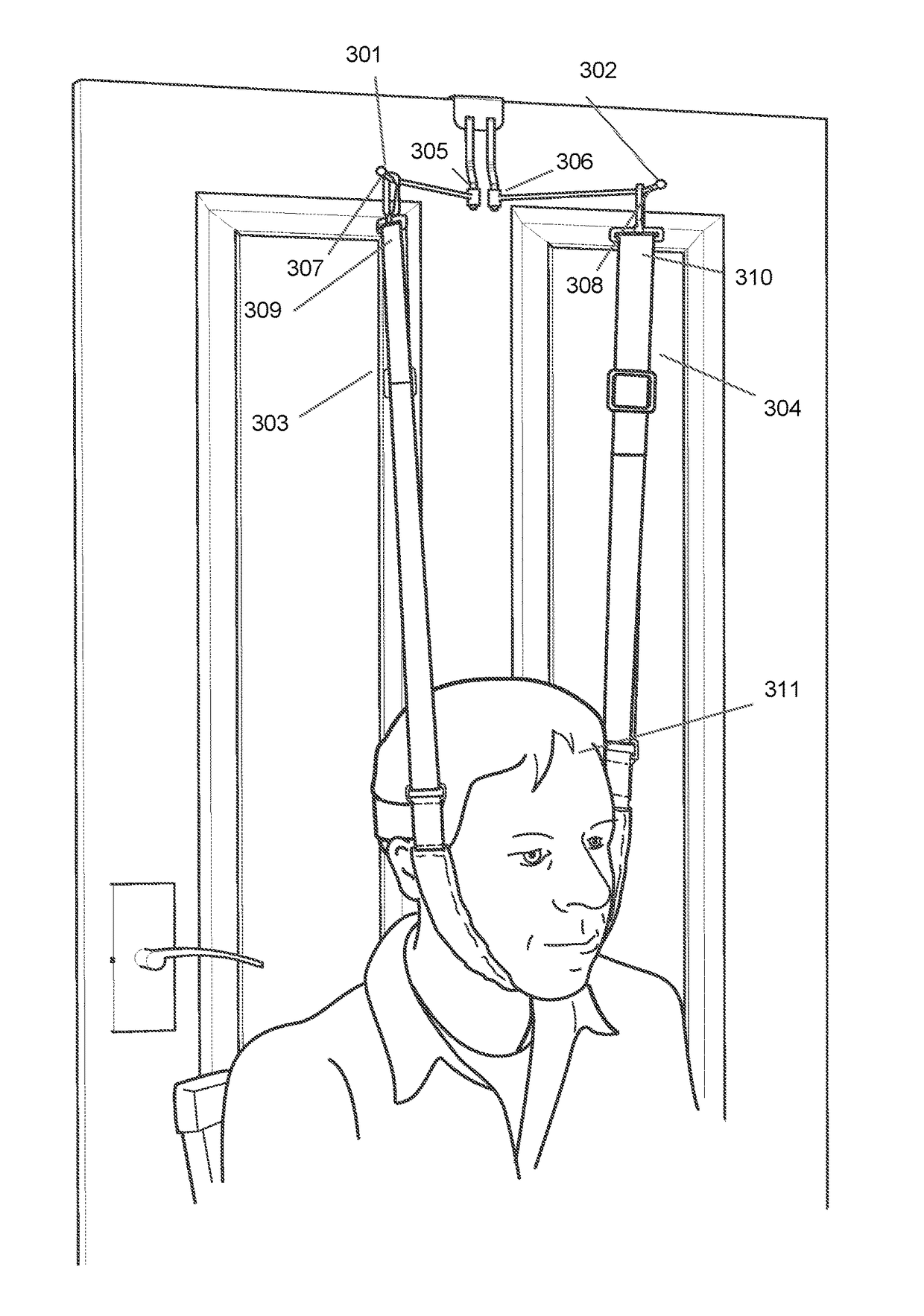
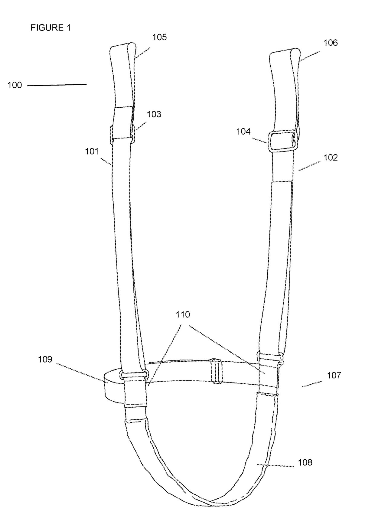
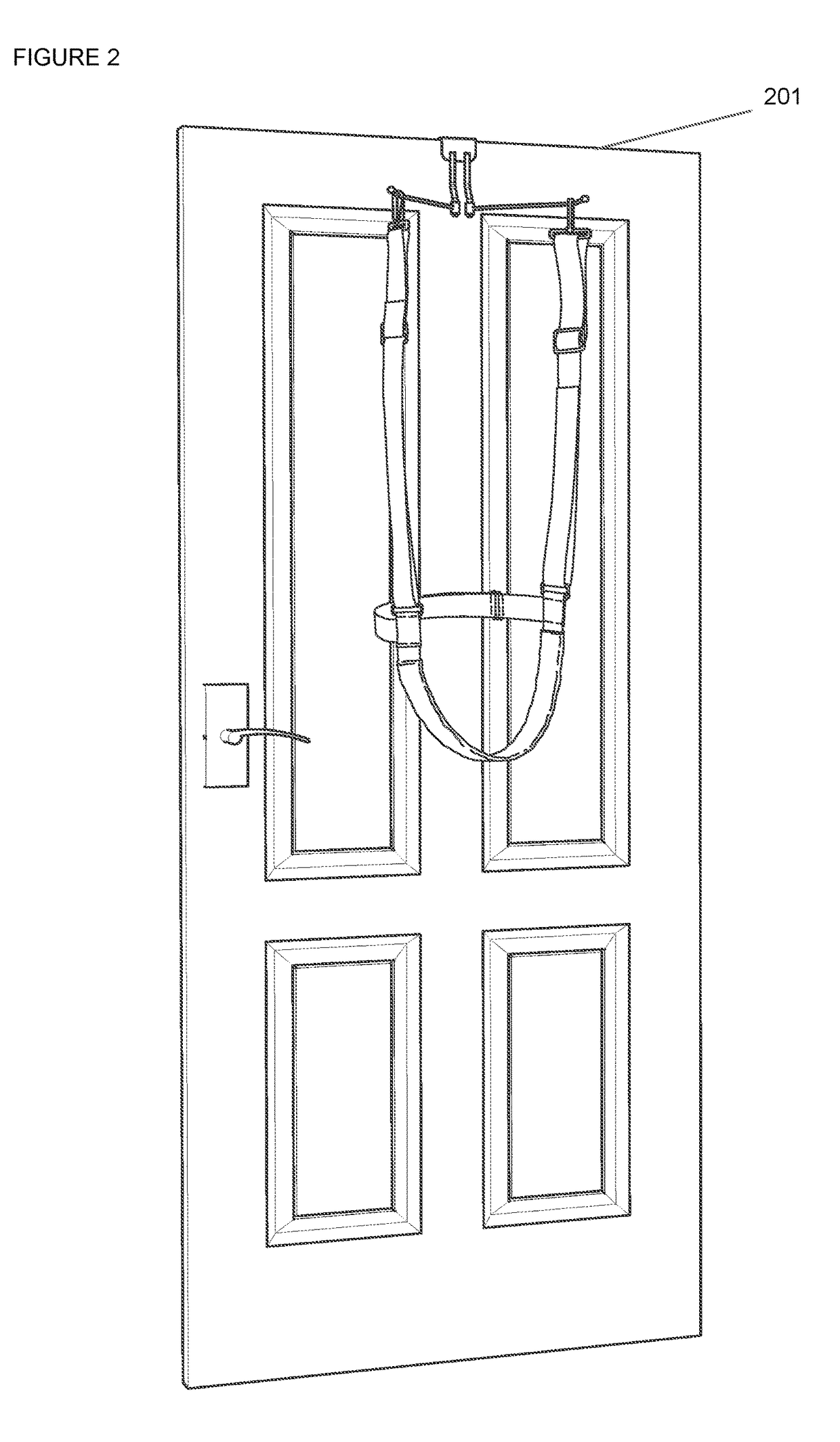
[0034]FIG. 1 provides an example of a preferred embodiment of the harness portion 100 of the device. The harness portion comprising two lengths of straps 101,102 with an adjustable means 103.104. The means for adjusting length 103,104 may be known technology in the art, comprising but not limited to sleeve through buckles, buttons, or hook and loop components. The length of each strap (of said first and second strap) should be long enough to extend from the top edge of a door 201 down, 311 towards the head of a person in seated position adjacent to said door to achieve the purpose of this invention (See FIGS. 2 and 3). Each said strap 101,102 having a top end 105,106 loosely connectable to the bracket portion device. The ability to loosely and removably connect to the bracket portion of the device is to enable the entire device to be broken down and taken a part for portability. The detachably connectable element may simply be a hook or sleeve feature that slides over or around each...


PUM


Abstract

The invention herein pertains to a spinal therapy device, system and method of use, specifically for self-administrating spinal decompression. The invention pertains to a method of lifting the user's upper spinal column by an extension device hooked over the top edge of a door jamb or floating wall, positioned over the user's head while the user is in seated position. The device comprising a hook portion, a strap portion and a harness portion and may be disassembled for portability.

Description

CROSS REFERENCE TO RELATED APPLICATIONS[0001]This nonprovisional patent application incorporates by reference in full its prior filed provisional Patent Application No. 62 / 398,687, and claiming priority to that earlier provisional filing date, Sep. 23, 2016, according to 35 USC 119(e).FEDERALLY SPONSORED RESEARCH OR DEVELOPMENT[0002]Not applicable.REFERENCE TO SEQUENCE LISTING, A TABLE, OR A COMPUTER LISTING APPENDIX[0003]Not applicable.COPYRIGHT NOTICE[0004]A portion of the disclosure of this patent document contains material that is subject to copyright protection. The copyright owner has no objection to the facsimile reproduction by anyone of the patent document or patent disclosure as it appears in the Patent and Trademark office, patent file or records, but otherwise reserves all copyright rights whatsoever.BACKGROUND OF THE INVENTIONField of the Invention[0005]The disclosed invention herein pertains to a spinal therapy device, system and method of use, particularly for self-ad...

Claims


Application Information

Patent Timeline
Patent Type & Authority Applications(United States)
IPC IPC(8): A61F5/042A61H1/02
CPCA61H1/0292A61F5/042A61F5/3707A61H2201/0123A61H2201/0192A61H2201/1607A61H2201/1652
Inventor KOVACEVIC, KRSTO
Owner KOVACEVIC KRSTO
Why Eureka
Try Eureka