Contact mechanism of electromagnetic relay

a contact mechanism and electromagnetic relay technology, applied in the direction of relays, non-polarised relays, contacts, etc., can solve the problems of electromagnetic relay b>1/b> not working,

Inactive Publication Date: 2018-04-05
DELTA ELECTRONICS INC
View PDF3 Cites 4 Cited by
  • Summary
  • Abstract
  • Description
  • Claims
  • Application Information

AI Technical Summary

Benefits of technology

[0007]It is an object of the present invention to provide a contact mechanism of electromagnetic relay for solving the problems of not smooth operation or stuck of the central axis which are caused by the accumulation of tiny dust or powder generated between the stationary contact head and the movable contact plate after long time use, and for avoiding the problem of the contact points being welded together due to the gap generated between the stationary contact head and the movable contact plate when surge current flows through the stationary contact head and the movable contact plate.

Problems solved by technology

Consequently, the movement of the central axis 122 is limited due to the accumulated dust or powder and the electromagnetic relay 1 fails to work.
Consequently, the stationary contact heads 113 and the movable contact plate 121 are welded together, which may result in the damage of the electromagnetic relay 1.

Method used


Image

  • Contact mechanism of electromagnetic relay
  • Contact mechanism of electromagnetic relay
  • Contact mechanism of electromagnetic relay

Examples


Embodiment Construction

[0019]The present invention will now be described more specifically with reference to the following embodiments. It is to be noted that the following descriptions of preferred embodiments of this invention are presented herein for purpose of illustration and description only. It is not intended to be exhaustive or to be limited to the precise form disclosed.

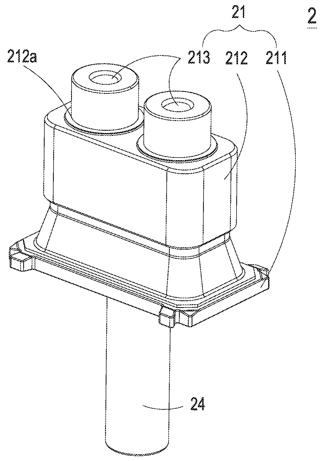
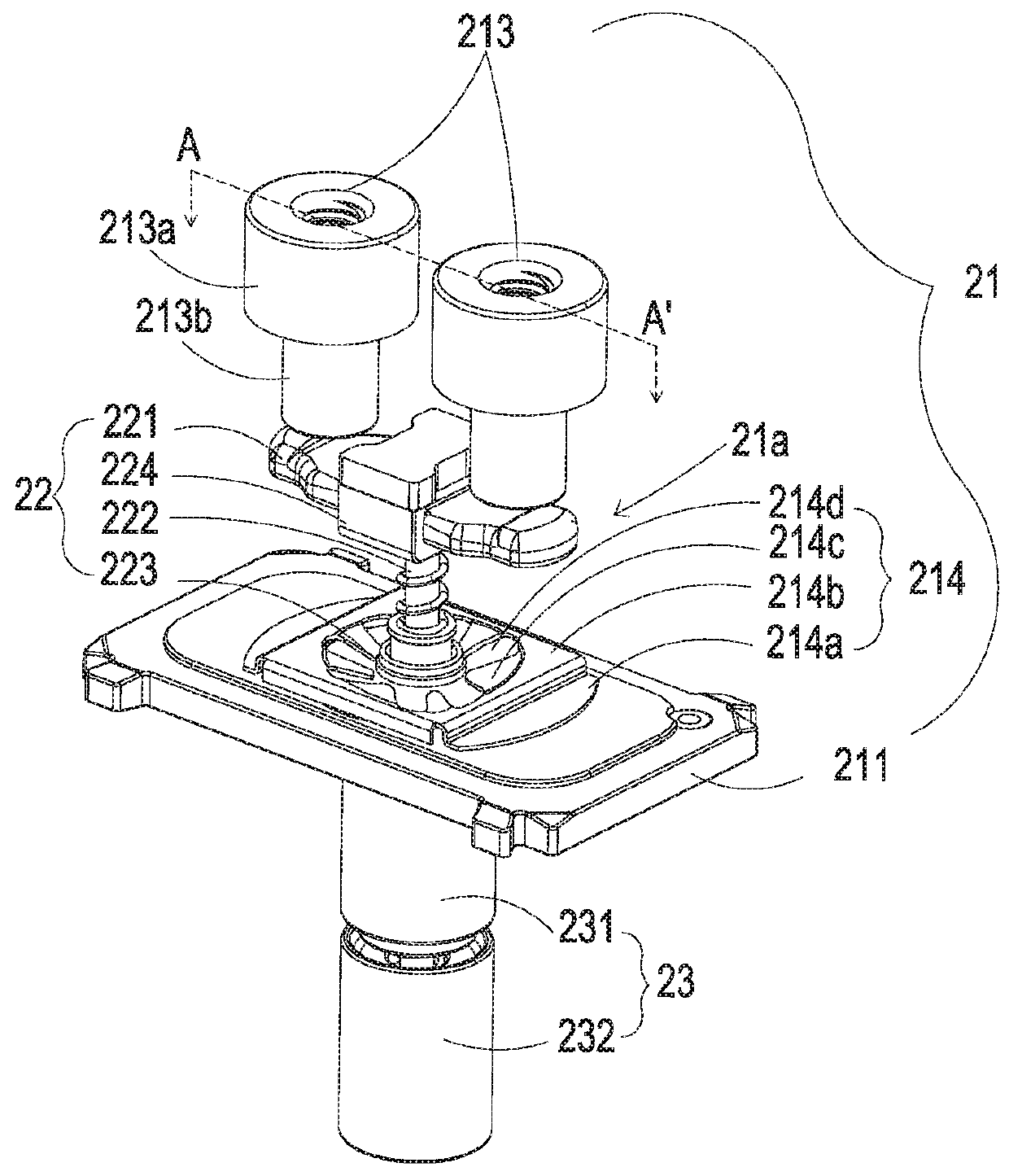
[0020]FIG. 2A is a schematic view illustrating the structure of the contact mechanism of electromagnetic relay according to a preferred embodiment of the present invention. FIG. 2B is a schematic perspective view illustrating the contact mechanism without the upper case and the tubular element of FIG. 2A. As shown in FIGS. 2A and 2B, the contact mechanism 2 of the present invention is applicable to an electromagnetic relay and includes a contact assembly 21, a movable contact assembly 22 and a driving unit 23. Please refer to FIG. 2A, the contact assembly 21 includes a bottom plate 211, an upper case 212 and two stationary contac...


PUM


Abstract

A contact mechanism of an electromagnetic relay comprises a contact assembly, a movable contact assembly and a driving unit. The contact assembly comprises a bottom plate, an upper case disposed on the bottom plate, and two stationary contact heads disposed on and penetrating the upper case. The movable contact assembly comprises a central axis passing through the contact assembly, a movable contact plate disposed on the top portion of the central axis and configured to contact with or separate from the two stationary contact heads, and a cover element covering the central portion of the central axis. The driving unit is disposed around the lower portion of the central axis and configured to drive the central axis to move back and forth along the axial direction for allowing the movable contact plate to contact with or separate from the two stationary contact heads.

Description

FIELD OF THE INVENTION[0001]The present invention relates to a contact mechanism, and more particularly to a contact mechanism of an electromagnetic relay.BACKGROUND OF THE INVENTION[0002]Recently, electromagnetic relay has been widely used in many fields, such as home appliance, industry, or automobile. The electromagnetic relay is employed to control a high-voltage working circuit through a low-voltage control circuit. That is, the electromagnetic relay is provided with a low voltage by the low-voltage control circuit, and the operation status of the high-voltage working circuit is controlled through the internal structure of the electromagnetic relay by means of electromagnetic principle.[0003]FIG. 1 is a cross-sectional view illustrating an electromagnetic relay of a prior art. As shown in FIG. 1, the conventional electromagnetic relay 1 includes a contact assembly 11, a movable contact assembly 12, a driving assembly 13, and a winding coil 14. The contact assembly 11 includes a...

Claims


Application Information

Patent Timeline
Patent Type & Authority Applications(United States)
IPC IPC(8): H01H51/04H01H45/04H01H45/14
CPCH01H51/04H01H45/14H01H45/04H01H50/54H01H1/54H01H50/023H01H50/026H01H50/20H01H50/42H01H50/546
Inventor LEE, MING-TSUNGWU, TSUNG-HSUENTIEN, CHING-HSIANG
Owner DELTA ELECTRONICS INC
Why Eureka
Try Eureka