Stacked ceramic resonator radio frequency filter for wireless communications

a ceramic resonator and radio frequency filter technology, applied in the field of electromechanical systems, can solve the problem of too large footprint of conventional ceramic resonator filters, and achieve the effect of small footprint and small footprin

Active Publication Date: 2018-04-05
SKYWORKS SOLUTIONS INC
View PDF0 Cites 3 Cited by
  • Summary
  • Abstract
  • Description
  • Claims
  • Application Information

AI Technical Summary

Problems solved by technology

However, this arrangement can result in a space problem where the footprint of the conventional ceramic resonator filter is too wide.

Method used


Image

  • Stacked ceramic resonator radio frequency filter for wireless communications
  • Stacked ceramic resonator radio frequency filter for wireless communications
  • Stacked ceramic resonator radio frequency filter for wireless communications

Examples


Embodiment Construction

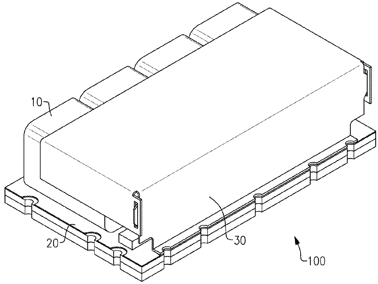
[0022]FIG. 1 shows a conventional ceramic resonator filter 100, which as a plurality resonators 10 (e.g., ceramic coaxial resonators) disposed adjacent each other and aligned along the same plane. The resonators 10 are disposed on a printed circuit board 20, and at least a portion of the resonators 10 is covered with a case 30. The conventional ceramic resonator filter 100 in FIG. 1 has four resonators. However, in other variations, the conventional ceramic resonator filter 100 can have fewer (e.g., 2) or more (e.g., 6, 8) resonators, all arranged adjacent each other along the same plane.

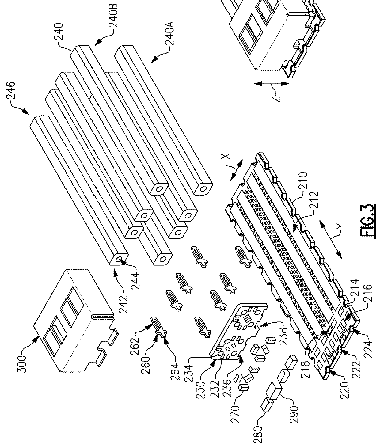
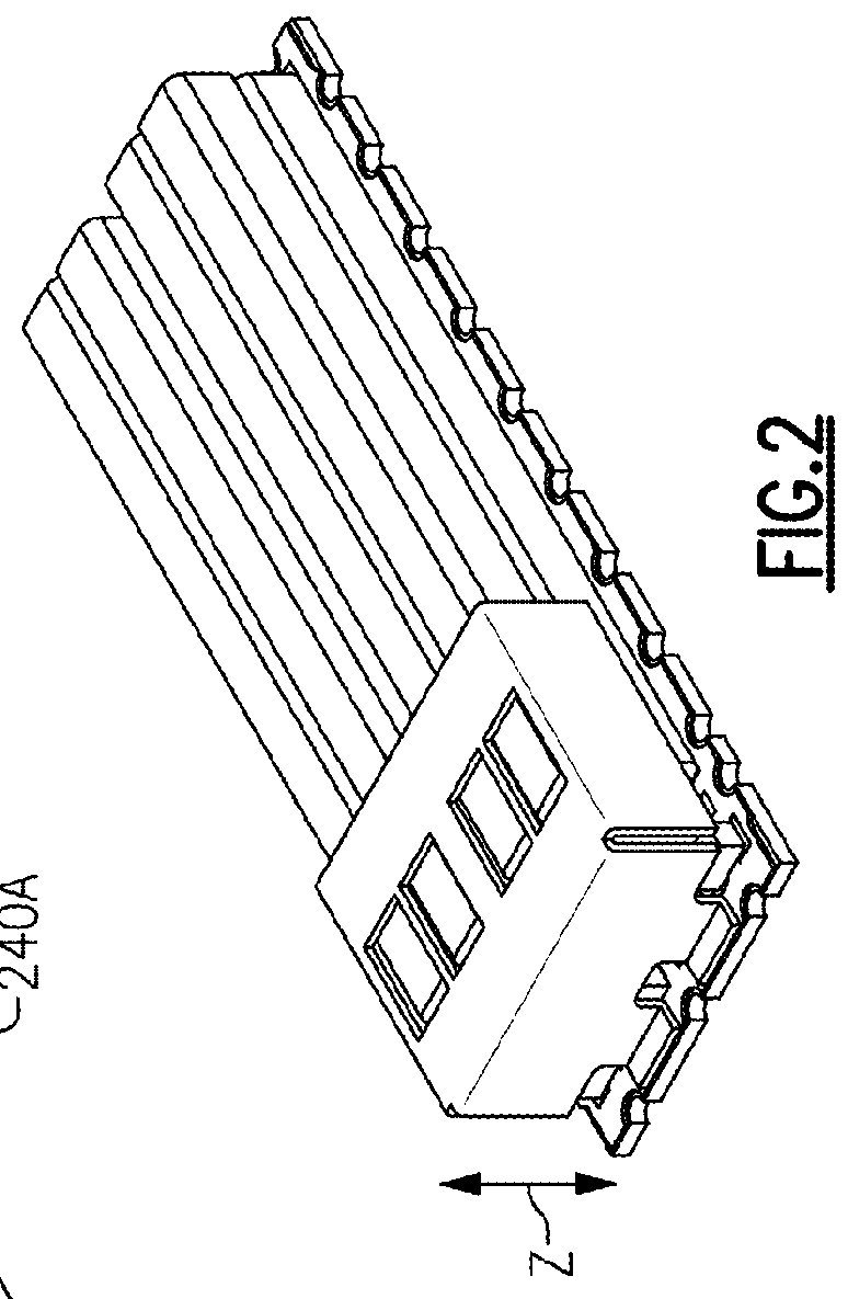
[0023]FIGS. 2-3 show one embodiment of an improved ceramic resonator filter assembly 200 (hereafter “filter assembly”) that can be used in radio frequency wireless applications. The filter assembly 200 can have a printed circuit board 210 with one or more strip pads 212. The printed circuit board 200 can extend along an X and Y direction. In the illustrated embodiment, the printed circuit board 200 ...


PUM


Abstract

A ceramic resonator radio frequency filter includes a printed circuit board, one or more first coaxial resonators disposed on the printed circuit board, and one or more second coaxial resonators disposed over the one or more first coaxial resonators so that the one or more first coaxial resonators and one or more second coaxial resonators are arranged in a stacked configuration. The one or more first coaxial resonators and second coaxial resonators electrically connected to the printed circuit board.

Description

INCORPORATION BY REFERENCE TO ANY PRIORITY APPLICATIONS[0001]Any and all applications for which a foreign or domestic priority claim is identified in the Application Data Sheet as filed with the present application are hereby incorporated by reference under 37 CFR 1.57.BACKGROUNDField[0002]Embodiments of the disclosure generally relate to electronic systems, and more particularly to ceramic resonator radio frequency filters for wireless communications.Description of the Related Art[0003]In conventional ceramic resonator filters, the resonators are arranged adjacent each other in a single plane. However, this arrangement can result in a space problem where the footprint of the conventional ceramic resonator filter is too wide.SUMMARY[0004]Accordingly, there is a need for ceramic resonator filters (for radio frequency wireless communications) that have a smaller footprint than conventional filter designs.[0005]In accordance with one aspect, a ceramic resonator filer (for radio frequen...

Claims


Application Information

Patent Timeline
Patent Type & Authority Applications(United States)
IPC IPC(8): H03H9/46H03H9/50H04B1/00H04B1/40
CPCH03H9/462H03H9/50H04B1/0057H04B1/40H01P1/2053H01P1/213H01P7/04H01P11/007
Inventor DARLING, JOHN KENNETHEIKER, BRIAN CHRISTOPHERBURK, ROBERT ALLENFRYE, MICHAEL R.
Owner SKYWORKS SOLUTIONS INC
Why Eureka
Try Eureka