
Microwave filter including an end-wall coupled coaxial resonator

A coaxial resonator and microwave filter technology, applied in waveguide devices, electrical components, circuits, etc., can solve problems such as increased insertion loss, high cost of filters, and difficulties in manufacturing coaxial resonators, achieving high flexibility , flexible cost-effective effect

Inactive Publication Date: 2008-05-21
PANASONIC CORP
View PDF1 Cites 5 Cited by
  • Summary
  • Abstract
  • Description
  • Claims
  • Application Information

AI Technical Summary

Problems solved by technology

[0015] A general problem with filters including coaxial resonators is that the coupling of the coaxial resonators imposes limitations on the flexibility in choosing an overall filter design suitable for a particular application
Accordingly, these filters are often associated with relatively high cost and / or high space requirements
Also, when coupling a coaxial resonator and a different type of resonator such as a dielectric resonator, the configuration in which the coaxial resonator rotates relative to the dielectric resonator has a disadvantage of being difficult to manufacture
While this disadvantage can be avoided by using a coupling loop or coupling probe that is bent to accommodate different field configurations for different resonator types, this configuration requires more components and increases insertion loss

Method used


Image

  • Microwave filter including an end-wall coupled coaxial resonator
  • Microwave filter including an end-wall coupled coaxial resonator
  • Microwave filter including an end-wall coupled coaxial resonator

Examples


Embodiment Construction

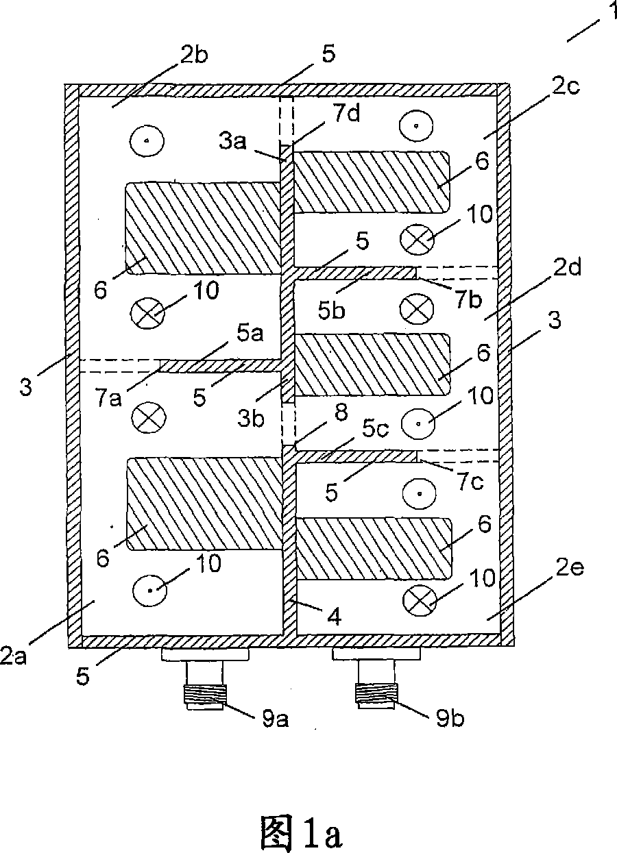
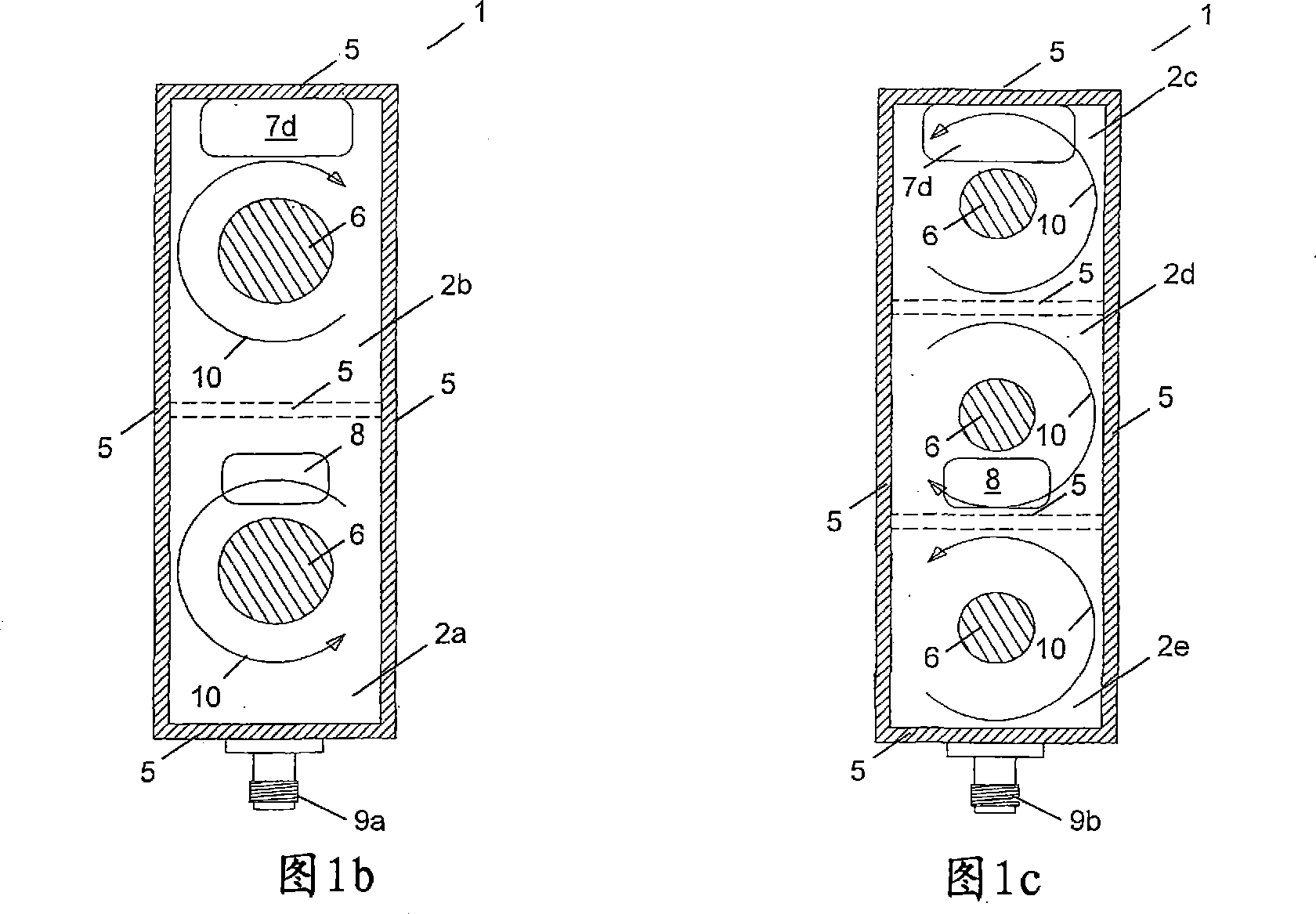
[0037] In Figures 1a to 1c a microwave filter 1 is shown. The filter 1 comprises five different coaxial resonators 2a, 2b, 2c, 2d and 2e having a rectangular cross-section and coupled in a two-dimensional array. Each of the coaxial resonators 2a to 2e comprises a hollow housing formed of a top wall or upper end wall 3 (the upper end walls of the resonators 2a and 2b are formed by a single plate-like portion, the upper end walls of the resonators 2c to 2e Also formed by a single plate-shaped part), the bottom wall or lower end wall 4 (the lower end walls of all resonators are formed by a single plate-shaped part), and the side walls 5 extending upwards from the respective lower end walls 4 (some of which are formed by the same plate-shaped element piece forming) constitutes. As can be understood from Figures 1b and 1c, the side walls 5 have a rectangular configuration comprising four interconnected wall sections arranged on four sides of the corresponding rectangular lower end...


PUM


Abstract

The present invention relates to a microwave filter comprising a plurality of coupled resonators (2a-2e, 22a-22g), wherein the plurality of coupled resonators (2a-2e, 22a-22g) includes at least one coaxial resonator (2a-2e, 22a-22b, 22g) comprising a housing having a lower end wall (4, 24), a sidewall (5, 25) extending upwardly from the lower end wall (4, 24) and an upper end wall (3, 23) and an inner conductor (6, 26) disposed within the housing and extending upwardly from the lower end wall (4, 24) along the longitudinal axis of the housing. At least one of the coaxial resonators (2a-2e, 22a-22b, 22g) comprises in its lower end wall (4, 24) and / or in its upper end wall (3, 23) a coupling means (7d, 8, 32) for effecting electromagnetic coupling of the respective coaxial resonator (2a- 2d, 22b, 22g) with an adjacent resonator.

Description

technical field [0001] The invention relates to a microwave filter comprising a plurality of coupled resonators including at least one coaxial resonator. Background technique [0002] The microwave region of the electromagnetic spectrum is widely used in various technical fields. Exemplary applications include wireless communication systems such as mobile communication and satellite communication systems, as well as navigation and radar technology. The growing number of microwave applications increases the possibility of interference within a system or between different systems. Therefore, the microwave region is divided into a number of different frequency bands. To ensure that a particular device communicates only within the frequency band assigned to that device, microwave filters are used to perform bandpass and bandstop functions during transmission and / or reception. Accordingly, the filters are used to separate different frequency bands and to distinguish between wa...

Claims


Application Information

Patent Timeline
IPC IPC(8): H01P1/205
CPCH01P1/2053
Inventor 迈克尔·霍夫特
Owner PANASONIC CORP
Learn More