
Material Handling Machine with Bucket Shake Control System and Method

a control system and material handling technology, applied in the direction of pump assemblies, servomotors, constructions, etc., can solve the problems of a large portion of the control of the shake control being taken out of the hands of the operator, and the typical operator having little control over the actual shake process,

Active Publication Date: 2018-04-12
WACKER NEUSON PRODN AMERICAS
View PDF0 Cites 15 Cited by
  • Summary
  • Abstract
  • Description
  • Claims
  • Application Information

AI Technical Summary

Benefits of technology

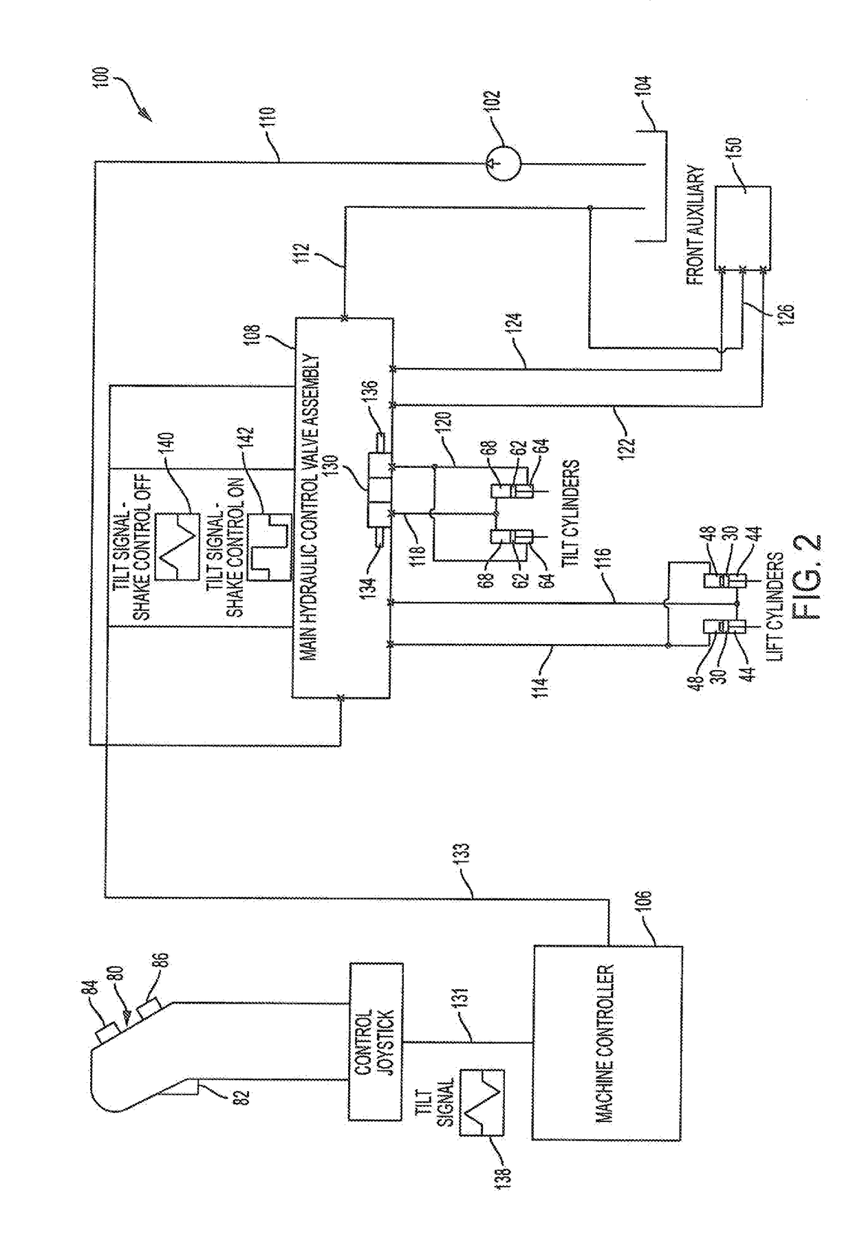
The invention provides a material handling machine with a mobile chassis, boom, bucket, tilt cylinder, and electrohydraulic control system. The electrohydraulic control system includes a source of pressurized fluid, a reservoir, a manually operated bucket tilt controller, an electronic controller, and a proportional control valve. The electronic controller is electronically coupled to the battery tilt controller and to the proportional control valve. The invention also provides a bucket shake control activation device and a method of effecting bucket shake control. The technical effect of this invention is that it allows for independent control of the bucket tilt rate and acceleration, regardless of the movement of the battery tilt controller. This improved efficiency and responsiveness in material handling machines reduces the time and effort required for operation.

Problems solved by technology

Most of these systems are rather complex in their configuration and / or operation.
Most of these systems also take a substantial portion of shake control out of the hands of the operator.
The typical operator thus has little control over the actual bucket shake process.
This lack of control over the process can be frustrating to some operators, particularly if the pre-programmed shake control is ineffective.
Many such systems also do not shake the bucket as aggressively as might be possible, again potentially reducing the effectiveness of the systems.

Method used


Image

  • Material Handling Machine with Bucket Shake Control System and Method
  • Material Handling Machine with Bucket Shake Control System and Method
  • Material Handling Machine with Bucket Shake Control System and Method

Examples


Embodiment Construction

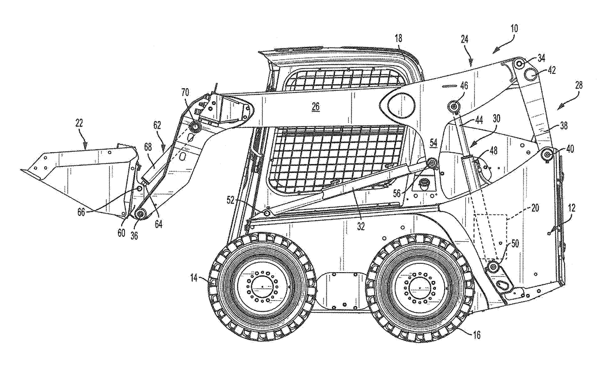
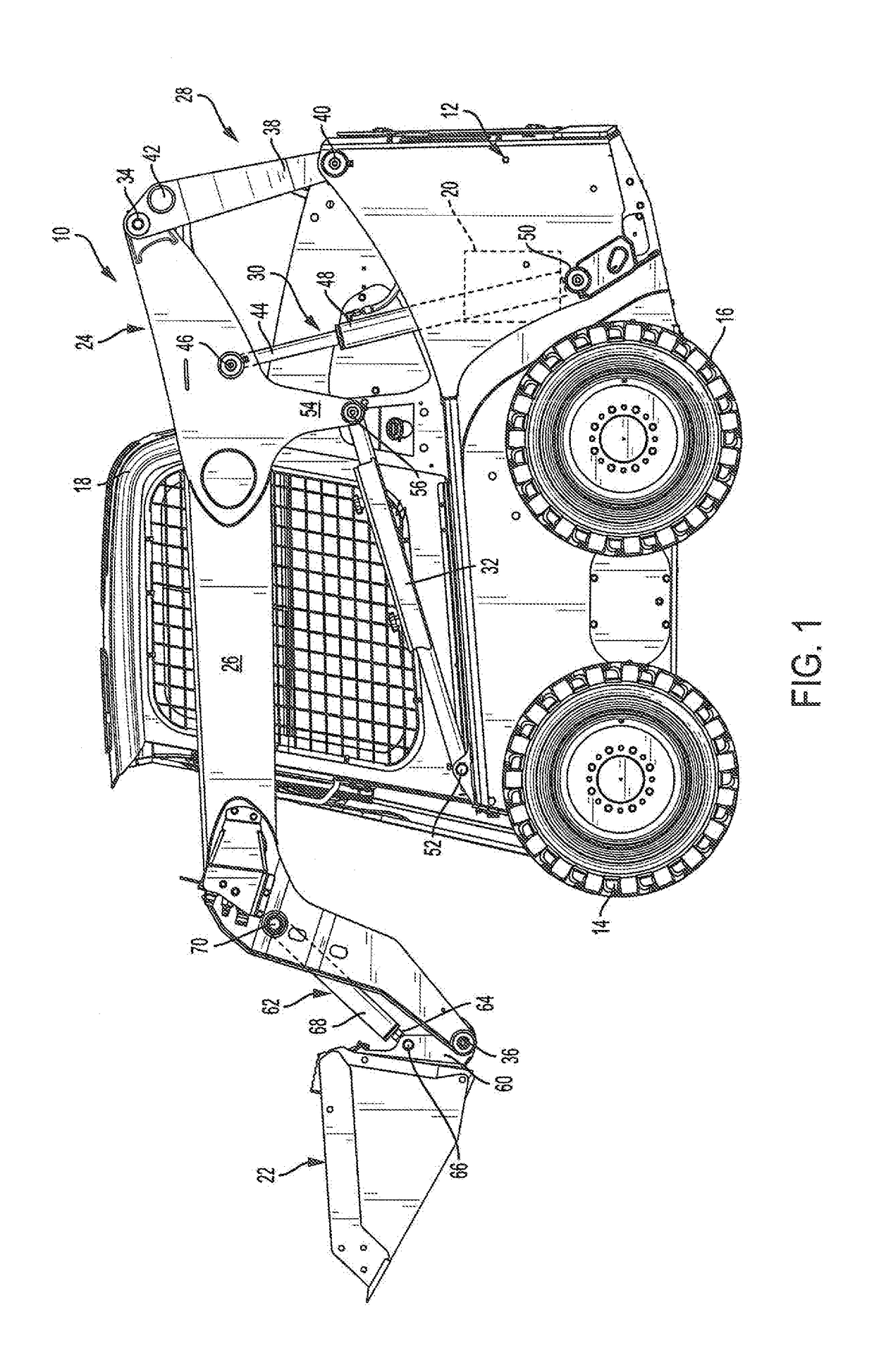
[0022]Referring to the drawings and initially to FIG. 1, a material handling machine 10 is illustrated that is fitted with a bucket shake control system constructed in accordance with the present invention. The illustrated machine 10 is a skid-steer loader having a vertical lift arrangement. However, the concepts discussed herein apply equally to a skid-steer loader having a radial lift arrangement, as well as to a variety of other material handling machines that are equipped with a bucket to excavate and / or transport materials such as soil, sand, gravel, etc. Such machines include, but are not limited to, wheel loaders, track loaders, telehandlers, backhoes, and excavators.

[0023]The illustrated machine 10 includes a chassis or frame 12 movably supported on the ground via wheels 14 and 16. The frame 12 supports an operator's cab 18, an engine 20, and all electronic and hydraulic control systems required to propel the machine 10 and to control, its powered devices. The frame 12 may b...


PUM


Abstract

A material handling machine can be operated in a bucket shake control mode to override proportional control of a valve controlling fluid flow to and from a bucket tilt cylinder of the machine. Fluid flow through the valve upon actuation of a tilt controller such a joystick therefore is proportional to actuator stroke when the shake control system is deactivated and is always maximized regardless of actuator stroke when the shake control system is activated. Bucket shake control is activated through the manual operation of a control device such as a joystick-mounted switch. As a result of this arrangement, proportional control valve actuation always occurs immediately upon bucket tilt controller movement in a direction that is dependent upon a direction of bucket tilt controller movement from the neutral position thereof

Description

BACKGROUND OF THE INVENTION1. Field of the Invention[0001]The invention relates to material handling machines such as skid-steer loaders or bucket loaders and, more particularly, relates to a material handling machine incorporating a bucket shake control system and method for shaking a bucket of the machine to clear lodged materials from the bucket.2. Discussion of the Related Art[0002]Material handling machines such as skid-steer loaders, wheel loaders, track loaders, telehandlers, and excavators often are equipped with a bucket to excavate and / or transport materials such as soil, sand, gravel, etc. The term “bucket” as used herein should be understood to mean any device utilized by a material handling machine to receive materials, move those materials from one location to another, and dump those materials. Buckets may be designed to excavate materials and / or to scoop piled materials and / or receive the materials from another machine.[0003]For example, the typical skid-steer loader ...

Claims


Application Information

Patent Timeline
Patent Type & Authority Applications(United States)
IPC IPC(8): E02F9/22F15B11/10F15B11/16
CPCE02F9/221E02F9/2228F15B11/10F15B11/16F15B2211/665F15B2211/426F15B1/26F15B2211/63F15B2211/411E02F3/3414F15B2211/3144F15B2211/6346F15B2211/6658
Inventor GREER, AARON
Owner WACKER NEUSON PRODN AMERICAS
Learn More