Fixing structure and electrical connection box

a technology of fixing structure and fixing box, which is applied in the direction of electrical/fluid circuit, electrical apparatus, vehicle components, etc., can solve the problem that the diameter of the attaching hole is larger than that of the typical attaching hole, and the axial force obtained by the attaching hole is not sufficient, so as to prevent axial force reduction

Active Publication Date: 2018-04-12
YAZAKI CORP +1
View PDF1 Cites 2 Cited by
  • Summary
  • Abstract
  • Description
  • Claims
  • Application Information

AI Technical Summary

Benefits of technology

[0007]In view of the aforementioned problems, the present invention is to provide a fixing structure and an electrical connection box capable of preventing axial force reduction in a tightened portion even when a hole diameter of an attaching hole is large.

Problems solved by technology

The electrical connection box provided with the attaching portion having an attaching hole the diameter of which is larger than that of a typical attaching hole hardly obtains sufficient axial force due to the bending of the plain washer or the neck of the attaching bolt when the attaching bolt and a nut are tightened even when the wide plain washer is used.

Method used


Image

  • Fixing structure and electrical connection box
  • Fixing structure and electrical connection box
  • Fixing structure and electrical connection box

Examples


first embodiment

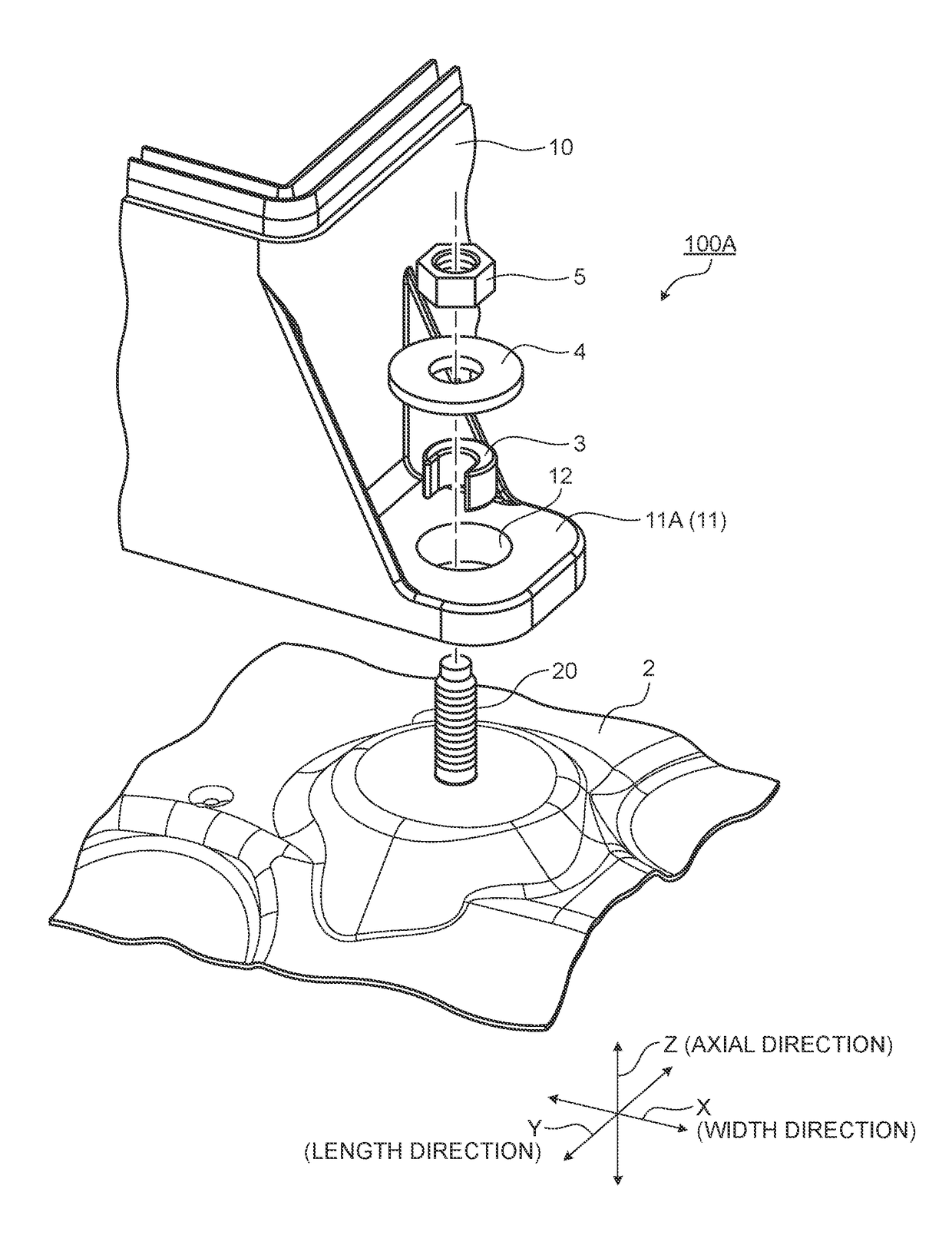
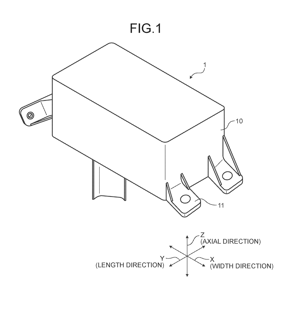
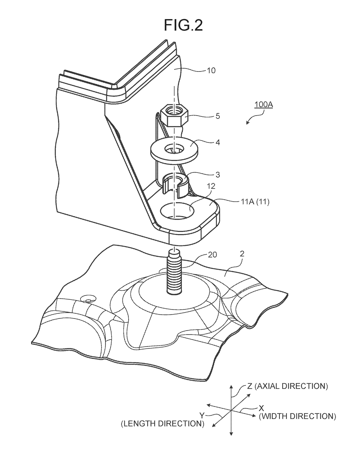
[0031]With reference to FIGS. 1 to 6, the following describes a fixing structure and an electrical connection box according to a first embodiment. FIG. 1 is a perspective view illustrating a schematic structure of the electrical connection box to which the fixing structure according to the first embodiment is applied. FIG. 2 is an exploded perspective view illustrating a schematic structure of the fixing structure according to the first embodiment. FIG. 3 is a perspective view illustrating the schematic structure of the fixing structure according to the first embodiment. FIG. 4 is a sectional view illustrating the schematic structure of the fixing structure according to the first embodiment. FIG. 5 is a plan view illustrating the schematic structure of the fixing structure according to the first embodiment. FIG. 6 is a perspective view illustrating a schematic structure of a spacer according to the first embodiment. FIG. 4 is a sectional view along line A-A of FIG. 3. FIG. 5 is a sc...

second embodiment

[0046]With reference to FIGS. 7 to 11, the following describes a fixing structure and an electrical connection box according to a second embodiment. FIG. 7 is an exploded perspective view illustrating a schematic structure of the fixing structure according to the second embodiment. FIG. 8 is a perspective view illustrating the schematic structure of the fixing structure according to the second embodiment. FIG. 9 is a sectional view illustrating the schematic structure of the fixing structure according to the second embodiment. FIG. 10 is a plan view illustrating the schematic structure of the fixing structure according to the second embodiment. FIG. 11 is a perspective view illustrating a schematic structure of a spacer according to the second embodiment. FIG. 9 is a sectional view along line B-B of FIG. 8. FIG. 10 is a schematic diagram illustrating the fixing structure according to the second embodiment viewed from the axial direction of the attaching bolt. FIG. 10 illustrates a s...

third embodiment

[0059]With reference to FIGS. 12 to 14, the following describes a fixing structure and an electrical connection box according to a third embodiment. FIG. 12 is an exploded perspective view illustrating a schematic structure of the fixing structure according to the third embodiment. FIG. 13 is a perspective view illustrating the schematic structure of the fixing structure according to the third embodiment. FIG. 14 is a sectional view illustrating the schematic structure of the fixing structure according to the third embodiment. FIG. 14 is a sectional view along line C-C of FIG. 13.

[0060]A fixing structure 100C according to the third embodiment differs in structure from the attaching portions and the spacers in the first and the second embodiments.

[0061]As illustrated in FIGS. 12 to 14, the fixing structure 100C according to the third embodiment includes an attaching portion 11C (11), the washer 4, and the nut 5.

[0062]The attaching portion 11C (11) includes a main body 112 and a cover...


PUM


Abstract

A fixing structure includes an attaching portion, a nut, and a spacer. The attaching portion has an attaching hole through which an attaching bolt provided to a vehicle body is inserted. The nut fixes the attaching portion to the vehicle body by being tightened to the attaching bolt with a washer interposed between the nut and the attaching portion. The spacer is disposed between an inner circumferential surface of the attaching hole and an outer circumferential surface of the attaching bolt, and is in contact with the vehicle body and the washer in an axial direction of the attaching bolt in a state where the attaching bolt and the nut are tightened. The spacer has an opening on a cylindrical side surface thereof and is capable of rotating around the axial direction of the attaching bolt in a state where the attaching bolt is inserted into the opening.

Description

CROSS-REFERENCE TO RELATED APPLICATION(S)[0001]The present application claims priority to and incorporates by reference the entire contents of Japanese Patent Application No. 2016-198283 filed in Japan on Oct. 6, 2016.BACKGROUND OF THE INVENTION1. Field of the Invention[0002]The present invention relates to a fixing structure and an electrical connection box.2. Description of the Related Art[0003]Electrical connection boxes (also called junction boxes, fuse boxes, or relay boxes) have been known that are mounted on vehicles such as automobiles and collectively house therein connection processing parts such as wire harnesses and electric components such as fuses, relays, and electric control units. The electrical connection boxes are made of resin materials having insulation property and fixed to vehicle bodies with various fixing structures (e.g., refer to Japanese Patent Application Laid-open No. 2011-78264 and Japanese Patent Application Laid-open No. 11-311219).[0004]An example o...

Claims


Application Information

Patent Timeline
Patent Type & Authority Applications(United States)
IPC IPC(8): H02G3/08B60R16/02
CPCH02G3/08B60R16/02H02G3/081B60R16/0238H02G3/10
Inventor TASHIRO, HIROKIKANEKO, NOBUTAKAOHASHI, FUMIYOSHIYONEZU, KOUJIYOSHIKAWA, YUYA
Owner YAZAKI CORP
Why Eureka
Try Eureka