
Helicopter rotor flapping hinge

A helicopter rotor and swing hinge technology is applied in the field of helicopters to achieve the effect of not easy to wear and good coaxiality

Active Publication Date: 2016-06-01
CHINA HELICOPTER RES & DEV INST
View PDF6 Cites 1 Cited by
  • Summary
  • Abstract
  • Description
  • Claims
  • Application Information

AI Technical Summary

Problems solved by technology

[0003] The purpose of the present invention is to provide a helicopter rotor flapping hinge, to solve or at least alleviate at least one problem of the rotor flapping hinge described in the technical background

Method used


Image

  • Helicopter rotor flapping hinge
  • Helicopter rotor flapping hinge
  • Helicopter rotor flapping hinge

Examples


Embodiment Construction

[0031] In order to make the objectives, technical solutions and advantages of the present invention clearer, the technical solutions in the embodiments of the present invention will be described in more detail below in conjunction with the drawings in the embodiments of the present invention. In the drawings, the same or similar reference numerals denote the same or similar elements or elements having the same or similar functions throughout. The described embodiments are some, but not all, embodiments of the invention. The embodiments described below by referring to the figures are exemplary and are intended to explain the present invention and should not be construed as limiting the present invention. Based on the embodiments of the present invention, all other embodiments obtained by persons of ordinary skill in the art without creative efforts fall within the protection scope of the present invention. Embodiments of the present invention will be described in detail below ...


PUM


Abstract

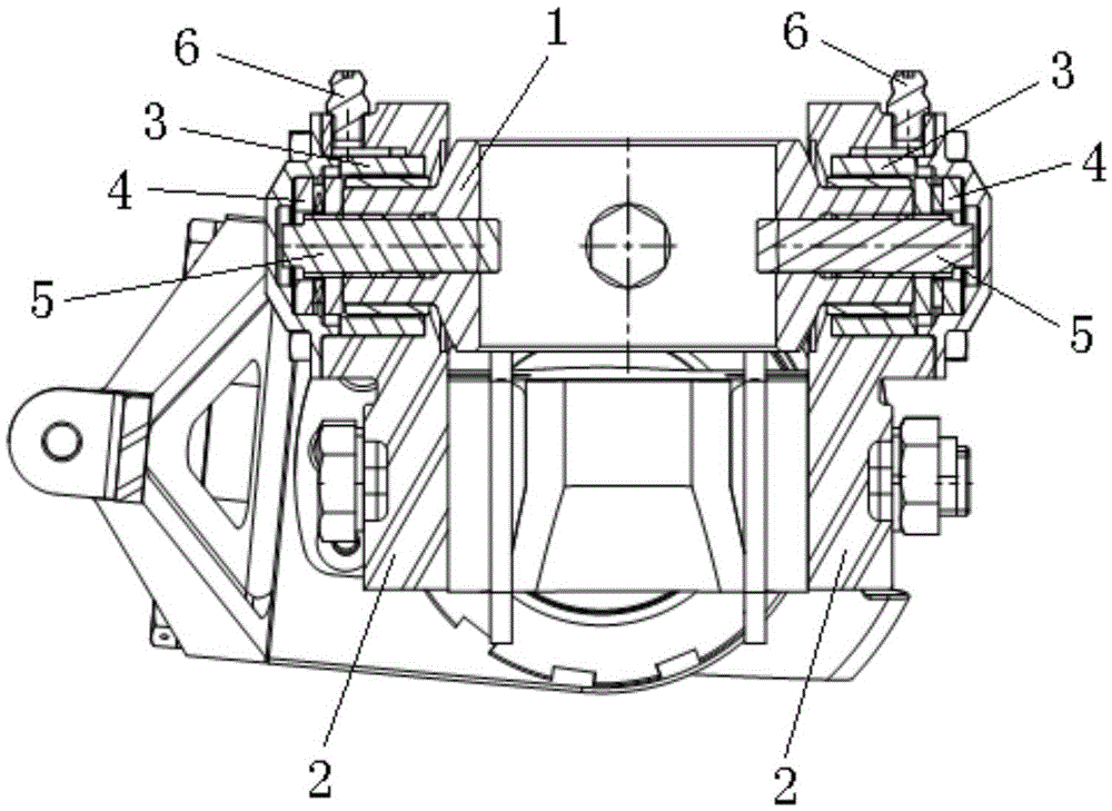
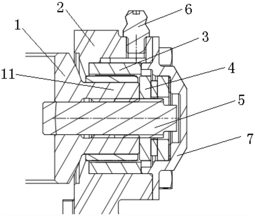
The invention discloses a helicopter rotor flapping hinge and relates to the technical field of helicopters. The helicopter rotor flapping hinge is installed on a rotor shaft (9) and comprises a lantern ring (1), two clamp plates (2) and two antifriction bearings (3), wherein the rotor shaft (9) is sleeved with the lantern ring (1) which rotates along with the rotor shaft (9), and bearing installation sections (11) are arranged on the circumferential outer side of the lantern ring (1) at a 180-degree interval; the two clamp plates (1) are arranged on the bearing installation sections (11) through the antifriction bearings (3), the axis of the antifriction bearings (3) is perpendicular to the axis of the rotor shaft (9), and the two clamp plates (1) are fixedly connected through a connector. The helicopter rotor flapping hinge has the advantages that the two clamp plates are arranged on the bearing installation sections through the antifriction bearings and are fixedly connected through the connector, the clamp plates swing around the lantern ring through the antifriction bearings, abrasion of the lantern ring and the clamp plates does not occur easily, and the service life of the flapping hinge is longer.

Description

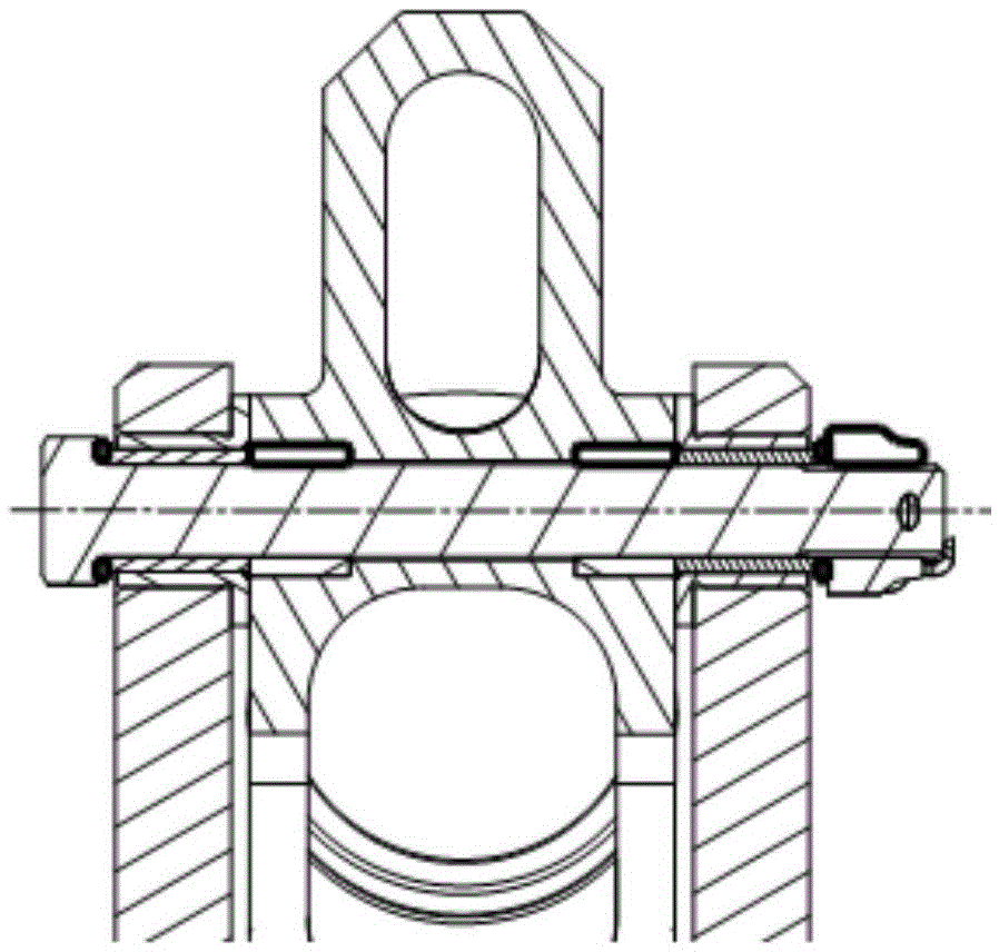
technical field [0001] The invention relates to the technical field of helicopters, in particular to a helicopter rotor flapping hinge. Background technique [0002] The structural arrangement of the swinging hinge of the helicopter rotor in the prior art generally directly uses a long bolt as the mounting platform and the swinging axis of the swinging hinge. The arrangement ( figure 1 ) The disadvantage is that because all the loads are borne by the long bolts, the long-term waving movement will cause damage to the bolts and bushings due to wear, the life of the bolts is very low, and the reliability is low. Contents of the invention [0003] The object of the present invention is to provide a helicopter rotor flapping hinge to solve or at least alleviate at least one problem existing in the rotor flapping hinge described in the technical background. [0004] The technical solution adopted by the present invention is to provide a helicopter rotor swinging hinge, which i...

Claims


Application Information

Patent Timeline
IPC IPC(8): B64C27/37
CPCB64C27/37
Inventor 赵青王健张昊邬文强
Owner CHINA HELICOPTER RES & DEV INST
Learn More