Systems and methods for containing ignition within a battery housing

a battery housing and battery technology, applied in the field of equipment dry bays, can solve the problems of affecting the service life of secondary cells, and affecting the service life of batteries

Active Publication Date: 2018-04-19
THE BOEING CO
View PDF2 Cites 21 Cited by
  • Summary
  • Abstract
  • Description
  • Claims
  • Application Information

AI Technical Summary

Problems solved by technology

One of the hazards of an ignition occurring is that pressures within an unvented bay may increase substantially.
Such foam blocks may impede access to equipment and may themselves be flammable.
However, in some implementations, such as a fuel tank equipment bay in a pressurized cabin, it may not be feasible or desirable—or even compliant with regulations—to vent excess pressure to the surrounding environment.

Method used


Image

  • Systems and methods for containing ignition within a battery housing
  • Systems and methods for containing ignition within a battery housing
  • Systems and methods for containing ignition within a battery housing

Examples


Embodiment Construction

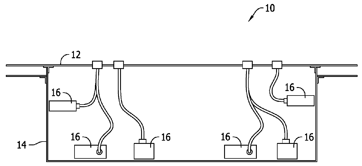
[0019]The systems and methods described herein provide an equipment dry bay that includes a partition. The partition subdivides the equipment dry bay into a first compartment and a second compartment. Further, the partition includes a plate and at least one flame arrestor positioned within the plate. Accordingly, in the event that an ignition occurs in the first compartment, combustion gases from the ignition vent into the second compartment through the flame arrestor. This substantially reduces pressure and temperatures generated by the ignition, and prevents the ignition from spreading to the second compartment.

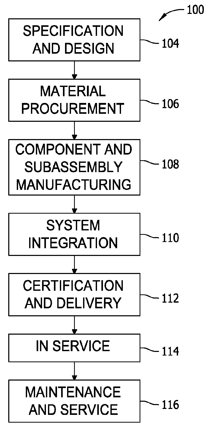
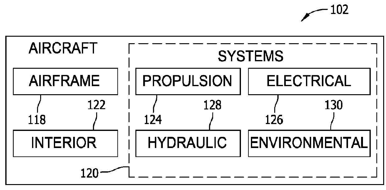
[0020]Referring more particularly to the drawings, implementations of the disclosure may be described in the context of an aircraft manufacturing and service method 100 as shown in FIG. 2 and an aircraft 102 as shown in FIG. 3. During pre-production, exemplary method 100 may include specification and design 104 of the aircraft 102 and material procurement 106. During produc...


PUM

PropertyMeasurementUnit
ignition pressureaaaaaaaaaa
pressureaaaaaaaaaa
pressureaaaaaaaaaa

Abstract

A battery housing including a plurality of side walls oriented to define an interior, and at least one partition that subdivides the interior into at least a first battery compartment and a second battery compartment. The at least one partition defines a flame arrestor configured to provide fluid communication between the first battery compartment and the second battery compartment such that combustion gases are ventable therebetween.

Description

CROSS-REFERENCE TO RELATED APPLICATIONS[0001]This application is a continuation-in-part and claims priority to U.S. patent application Ser. No. 14 / 193,002 filed Feb. 28, 2014 for “SYSTEMS AND METHODS FOR CONTAINING IGNITION WITHIN EQUIPMENT DRY BAYS,” which is hereby incorporated by reference in its entirety.BACKGROUND[0002]The field of the disclosure relates generally to equipment dry bays, and, more particularly, to mitigating effects of ignitions (e.g., explosions) that may occur in an equipment dry bay.[0003]Fuel tanks and other systems typically include one or more equipment dry bays, such as the conventional equipment dry bay 10 shown in FIG. 1. Equipment dry bay 10 is defined by an outer wall 12 and an inner wall 14, and includes a plurality of pieces of electrical equipment 16. In the event that fuel leaks into equipment dry bay 10, faults in electrical equipment 16 may ignite the leaked fuel.[0004]Accordingly, Federal Aviation Regulations require that areas where flammable ...

Claims


Application Information

Patent Timeline
Patent Type & Authority Applications(United States)
IPC IPC(8): B64D37/32B64D37/08H01M2/10H01M10/44H01M10/48H01M2/12A62C4/00A62C3/08A62C3/16A62C3/06H01M50/204H01M50/291H01M50/293
CPCB64D37/32B64D37/08H01M2/1077H01M10/441H01M10/482H01M2/127A62C4/00A62C3/08A62C3/16A62C3/065B64D2045/009H01M2220/20H01M2200/00H01M2010/4271A62C3/07Y02E60/10H01M50/383H01M50/394H01M50/293H01M50/204H01M50/291
Inventor TWEET, TRACY LEEDOVE, MICHAEL KENT
Owner THE BOEING CO
Why Eureka
Try Eureka