
Fluid flow rate measuring and gas bubble detecting apparatus

a flow rate and detection apparatus technology, applied in the direction of instruments, diagnostic recording/measuring, ultrasonic/sonic/infrasonic diagnostics, etc., can solve the problems of dam not disclosing a circuit for detecting hematocrit and/or hemoglobin, and more expensive to manufacture, deploy and maintain

Active Publication Date: 2018-04-26
MAQUET CARDIOPULMONARY GMBH
View PDF4 Cites 20 Cited by
  • Summary
  • Abstract
  • Description
  • Claims
  • Application Information

AI Technical Summary

Benefits of technology

The patent is for a device that can sense and detect bubbles in fluid flowing through a tube, which can help to improve the accuracy of fluid flow measurement. The device includes a sensor that measures the flow rate, a sensor that detects bubbles, and a temperature sensor that measures the temperature of the fluid. By using this information, the device can calculate a temperature corrected fluid flow rate, which corrects for temperature effects on the flow measurement. The technical effect of this invention is to provide a more reliable and accurate method for monitoring fluid flow in medical equipment.

Problems solved by technology

However, a disadvantage to such systems would be their complexity of construction, which makes them more costly to manufacture, deploy and maintain.
However, Dam does not disclose a circuit for detecting hematocrit and / or hemoglobin of blood in a tube.

Method used


Image

  • Fluid flow rate measuring and gas bubble detecting apparatus
  • Fluid flow rate measuring and gas bubble detecting apparatus
  • Fluid flow rate measuring and gas bubble detecting apparatus

Examples


Embodiment Construction

[0026]Various illustrative, non-limiting embodiments of this disclosure are described as follows with reference to the drawings, in which like parts are designated with like character references. First, one or more non-limiting apparatus embodiments are described, and then one or more non-limiting method embodiments are described.

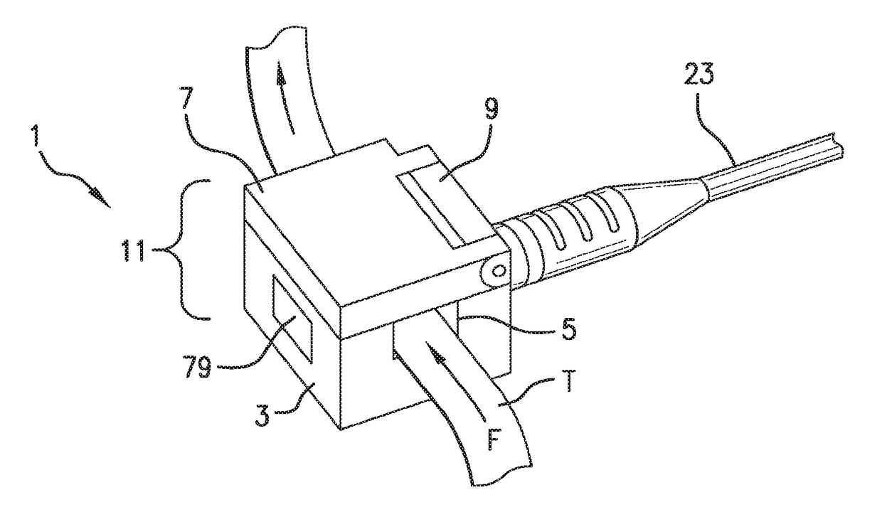
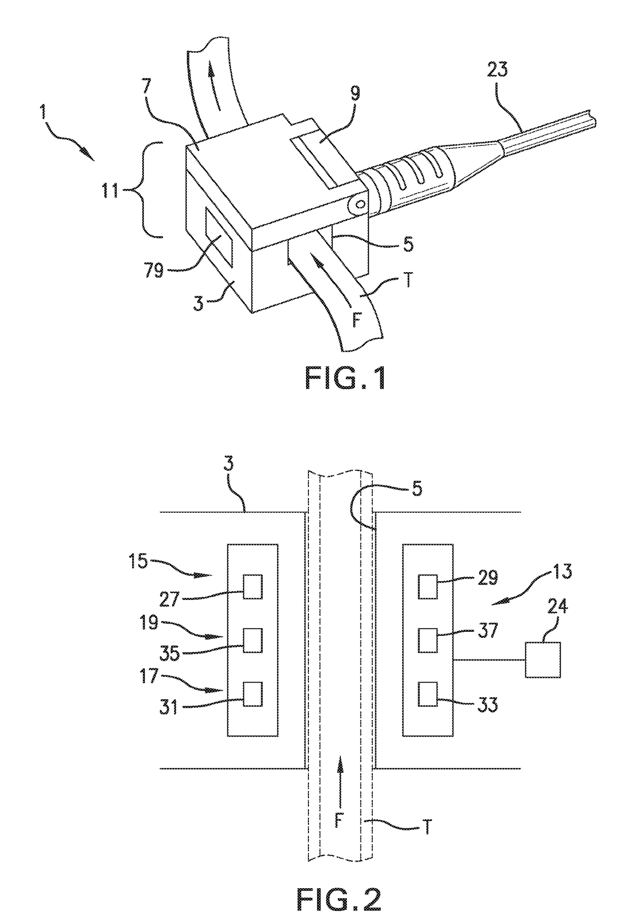
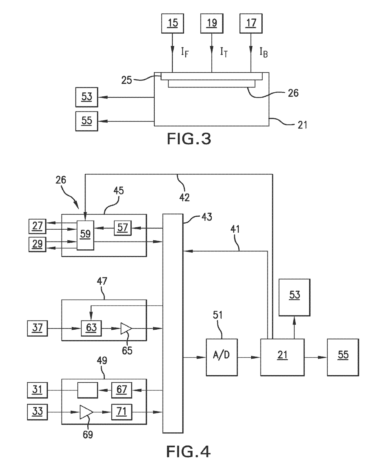
[0027]FIG. 1 illustrates a fluid flow sensing bubble detecting apparatus 1 that includes a main housing 3 provided with a channel 5 configured to receive a tube T through which fluid F flows. The tube T may be connected to medical equipment, such as a kidney dialysis machine, an infusion pump blood analyzer, a transfusion system, an extracorporeal membrane oxygenation (ECMO) machine, or a cardio-pulmonary bypass machine, or the tube T may be a component of a tubing set connected to such medical equipment. The fluid flowing in tube T may, thus, be blood; however, it may also be other kinds of physiologic fluids that include proteins, electrolytes, volume exp...


PUM


Abstract

A fluid flow sensing and bubble detecting apparatus includes a housing comprising a channel configured to receive a tube through which fluid flows; a sensor apparatus disposed within the housing, which includes a first sensor operable to measure flow rate of fluid and to detect bubbles in flowing fluid; and a temperature sensor operable to detect temperature of the flowing fluid; and a processor connected to receive fluid flow rate data obtained by the first sensor, to receive bubble detection data obtained by the first sensor, and to receive fluid temperature data obtained by the temperature sensor, wherein when a tube through which fluid flows is disposed in the channel of the housing, the first sensor measures the flow rate of the flowing fluid and detects bubbles therein, and the temperature sensor measures the temperature of the flowing fluid, and the processor calculates in a short period of time a fluid flow rate corrected for temperature. All sensors are non-invasive and have no direct contact to the fluid in the tube, which might be blood. In accordance with additional embodiments, the fluid flow rate is additionally corrected for hemoglobin or hematocrit, and the effect of oxygen saturation on the hemoglobin or hematocrit data.

Description

FIELD OF THE DISCLOSURE[0001]The field of the present disclosure pertains to that of fluid flow rate sensing apparatuses and bubble detecting apparatuses, such as may be used to determine the flow rate of fluid in a tube or pipe, and which may be used to detect gas bubbles in the fluid in the tube or pipe. More specifically, the present disclosure pertains to fluid flow rate measuring and gas bubble detecting apparatuses, such as operate to both determine the flow rate of a fluid and to detect the presence or absence of bubbles in a fluid. The present disclosure further pertains to use of the aforementioned fluid flow rate measuring and gas bubble detecting apparatuses in one or more systems and medical procedures, including those relating to extracorporeal blood circuits and systems, more specifically cardiopulmonary systems and procedures involving the movement of blood to and / or from the heart via pumps replacing all or a portion of the pumping activity typical of a beating heart...

Claims


Application Information

Patent Timeline
IPC IPC(8): A61M1/36G01F1/66
CPCA61M1/3626A61M1/3663G01F1/66A61M2205/3334A61M2205/3368A61M2205/3375A61M1/1698A61M1/3666A61M1/3627A61B5/01A61B5/14542A61B8/06A61B8/4477G01D21/02A61M2205/3313A61M1/3623A61B5/026A61B8/5223A61M1/14A61M39/281G01F1/668G01F15/022G01F1/662G01F1/667G01F1/74G16H50/30G01F1/00
Inventor LODERER, CHRISTIANASHTON, WESLEY SCOTT
Owner MAQUET CARDIOPULMONARY GMBH
Learn More