Rechargeable Bicycle Light System

a bicycle light and rechargeable technology, applied in the field of bicycle lights, can solve the problem that the light cannot be powered, and achieve the effect of reliable waterproofing and compact configuration

Inactive Publication Date: 2018-04-26
LIGHT & MOTION INDS
View PDF11 Cites 12 Cited by
  • Summary
  • Abstract
  • Description
  • Claims
  • Application Information

AI Technical Summary

Benefits of technology

[0006]The extending USB blade is part of a contiguous circuit board that houses all the related electronics required to drive the LED. This makes the design very cost effective.
[0016]The light of the invention is also useful as an underwater diving light, with its reliable waterproofing and compact configuration.

Problems solved by technology

Thus, once the USB is pulled out of the mounting device, the light cannot be powered.

Method used


Image

  • Rechargeable Bicycle Light System
  • Rechargeable Bicycle Light System
  • Rechargeable Bicycle Light System

Examples


Embodiment Construction

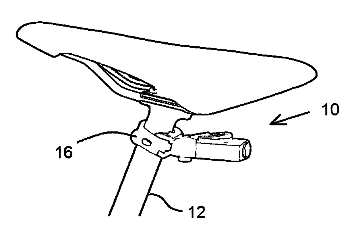
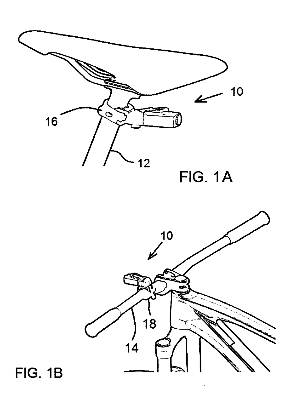
[0036]FIGS. 1A and 1B show the bicycle light assembly 10 of the invention attached to a bicycle, i.e. to a bicycle seat post 12 and to a handlebar 14, respectively. These connections to the bike can be made using connectors such as on Light & Motion Industries Urban bicycle light mountings, which can be seen at lightandmotion.com. As the drawings illustrate, mounting brackets 16 and 18 (preferably with stretchable bands as shown) are secured to the seat post or to the handlebar, and these mounting brackets, as on the Urban bicycle light, have a slot (not shown) onto which the light assembly 10 slides to firmly retain it in place. However, other types of connection could be used.

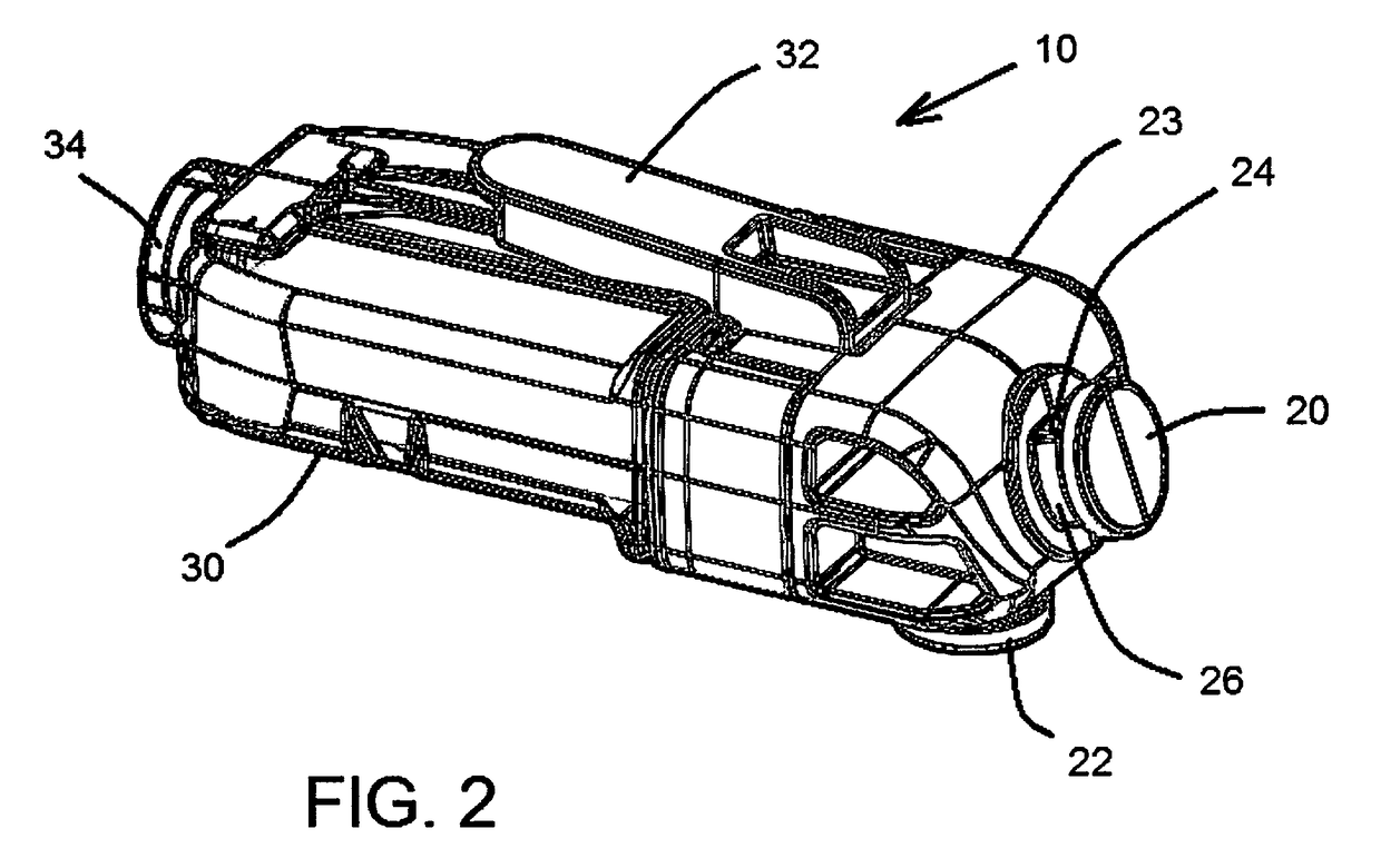
[0037]FIG. 2 shows the light assembly 10 without connection to any bicycle bracket. FIG. 2 shows button mounts or “mushroom” mounts 20 and 22 at different orientations on a base portion 23 of the light assembly. These are oriented and configured to be received in slots on the bike bracket, e.g. for handlebar ...


PUM


Abstract

A bicycle tail light or front light has a mounting base to connect to the bicycle, and an LED light unit for insertion into and removal from the base. The light unit includes a printed circuit board with LED driver and a rechargeable battery, all of which are encapsulated by a direct overmolding that forms a casing for the unit. For charging the light unit is pulled out from the base and plugged into a USB port. A tongue with USB blade at the back of the light unit functions to secure the light unit to the mounting base, and the attachment of the units switches power to the light unit. A motion detector on the PCB shuts off the LED if no motion is detected for several minutes, thus eliminating need for any exterior switch.

Description

BACKGROUND OF THE INVENTION[0001]The invention concerns bicycle lights in particular, but also other rechargeable lights such as worn on the body or on a helmet, and specifically the invention is concerned with a light unit contained in but readily removable from a housing and rechargeable using USB.[0002]A large number of different rechargeable bicycle lights have been known, many of them currently marketed. In at least one case the bicycle light had a USB connection blade at rear, the light assembly being contained within a molded casing to be mounted to the bicycle handlebar, seat post or other structure. A back end of the light, separate from the mount, could be removed from the main part of the light's casing to expose a USB contact blade. In order to recharge the battery of the light assembly using the USB connection, the light had to be removed from the bicycle and plugged into a suitable USB port, or a USB extension cord could be brought to the light. With such an assembly t...

Claims


Application Information

Patent Timeline
Patent Type & Authority Applications(United States)
IPC IPC(8): B62J6/00F21V23/00B62J6/02B62J6/04B62J6/16
CPCB62J6/005F21V23/004B62J6/02B62J6/04B62J6/16B62J2006/006F21V31/005F21L4/08F21Y2115/10B62J2300/008F21V21/406F21L4/027B62J6/01B62J45/41B62J6/029B62J6/03B62J6/057
Inventor EMERSON, DANIEL T.ARMER, JARODMCGEEVER, BENJAMINHEISS, DAVIDGOVAN, KEVINSIMON, ERICTOLAN, DAVID WILLIAM
Owner LIGHT & MOTION INDS
Why Eureka
Try Eureka