

Impedance measuring device
- Summary
- Abstract
- Description
- Claims
- Application Information
AI Technical Summary
Benefits of technology
Problems solved by technology
Method used
Image

Examples
first embodiment
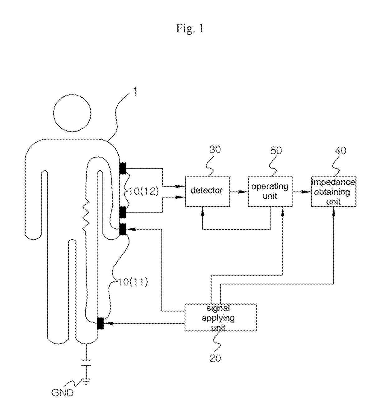
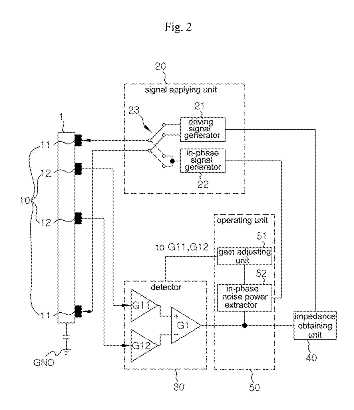
[0028]FIG. 1 is a block diagram schematically illustrating an impedance measuring device according to the present invention, and FIG. 2 is a block diagram specifically illustrating the impedance measuring device.
[0029]According to the first embodiment of the present invention, the impedance measuring device comprises an electrode 10, a signal applying unit 20, a detector 30, an operating unit 50, and an impedance obtaining unit 40.
[0030]There may be provided a plurality of electrodes 10 that contact an object 1 and spaced apart from each other and that include two driving electrodes 11 connected to the signal applying unit 20 and two sensing electrodes 12 connected to the detector 30. The same electrode may be used as the driving electrode 11 and the sensing electrode 12.
[0031]Here, when bringing the two driving electrodes 11 and two sensing electrodes 12 in contact to the object 1, an influence by signals applied to the two driving electrodes 11 is detected by the two sensing elect...
second embodiment
[0046]FIG. 3 is a block diagram specifically illustrating an impedance measuring device according to the present invention.
[0047]For the second embodiment, the pair of detectors 30-1 and 30-2 and operating unit 60 as components different from the first embodiment of the present invention are described.
[0048]According to the second embodiment of the present invention, there are two detectors 30 including a first detector 30-1 and a second detector 30-2 in which before differential-operated by a differential operator, detection signals of two sensing electrodes 12 are unequally amplified by their respective corresponding amplifiers so that one of the detection signals of the sensing electrodes may be amplified to have a relatively higher gain than the other detection signal of the sensing electrodes.
[0049]Further, a detection signal of the sensing electrode detected to have a relatively higher gain by the first detector 30-1 is rendered to be different from a detection signal of the s...
third embodiment
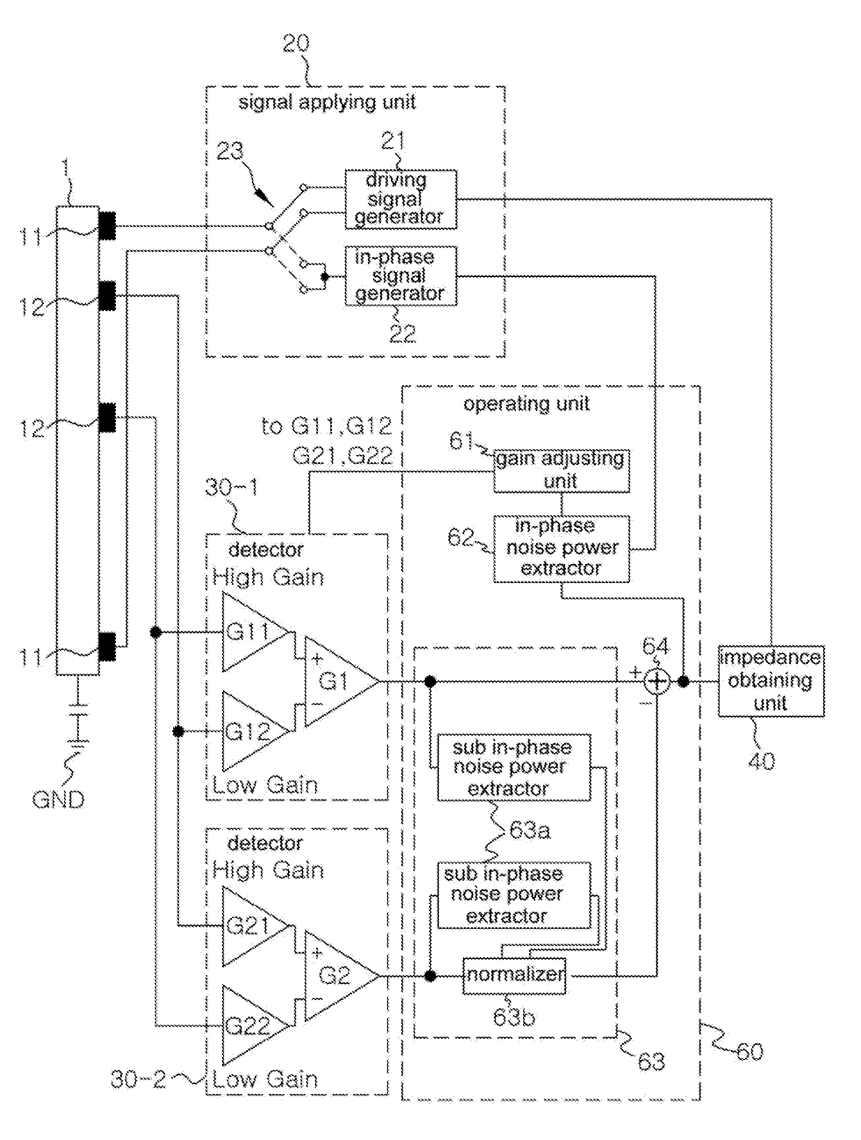
[0077]FIG. 4 is a block diagram specifically illustrating an impedance measuring device according to the present invention.
[0078]According to the third embodiment shown in FIG. 4, a first detector 30-1, a second detector 30-2, and an in-phase noise suppressor 64 have a different configuration from that in the second embodiment described with reference to FIG. 3.
[0079]First, the first detector 30-1 and second detector 30-2 are described. The input terminal of the differential operator in the first detector 30-1, which receives a relatively highly amplified detection signal, and the input terminal of the differential operator in the second detector 30-2, which receives a relatively highly amplified detection signal, are reverse polarities with respect to each other.
[0080]Specifically, it is the same as in the second embodiment that a relatively highly amplified one of detection signals from the two sensing electrodes 12 in the first detector 30-1 differs from a relatively highly ampli...
PUM
 Abstract
Description
Claims
Application Information