
Site light

a technology for site lights and light fixtures, applied in the field of site lights, can solve the problems of general limitations in the ability of current light systems

Active Publication Date: 2018-05-03
MILWAUKEE ELECTRIC TOOL CORP
View PDF6 Cites 12 Cited by
  • Summary
  • Abstract
  • Description
  • Claims
  • Application Information

AI Technical Summary

Benefits of technology

The invention is a site light that can adjust its arm length to change the height of the light. It also has a movable light assembly and a cable that connects to a power system. Another aspect of the invention is a body with an adjustable arm and a stowed and deployed position for a contact surface. The technical effects of this invention include the ability to easily adjust the light's arm length and the potential for flexibility and mobility in the position of the contact surface.

Problems solved by technology

In such instances, current light systems are generally limited in their ability to compensate for the difficulties of working in remote areas such as, for example, uneven terrain, the lack of an external power source, and movement within the site.

Method used


Image

  • Site light
  • Site light
  • Site light

Examples


Embodiment Construction

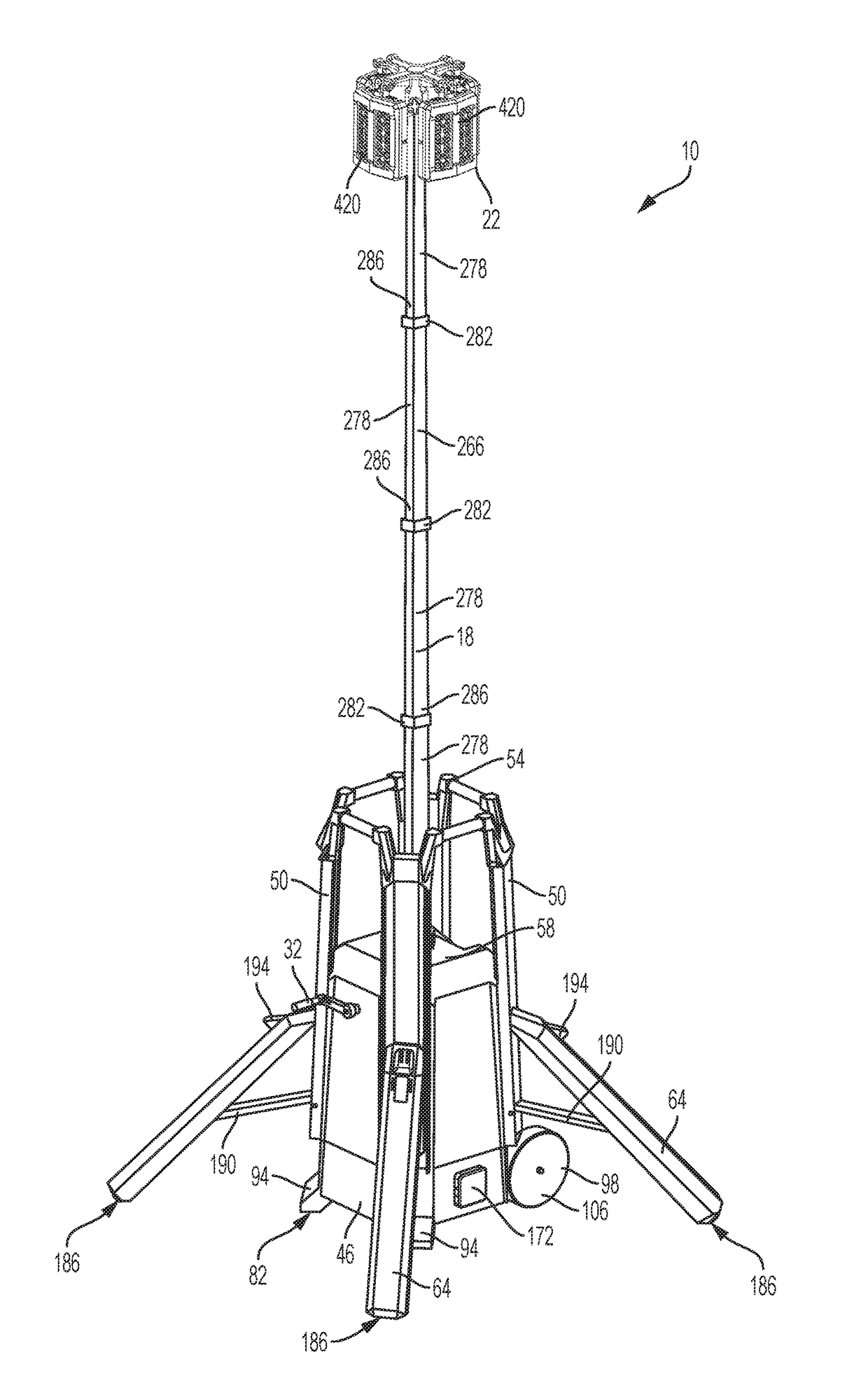
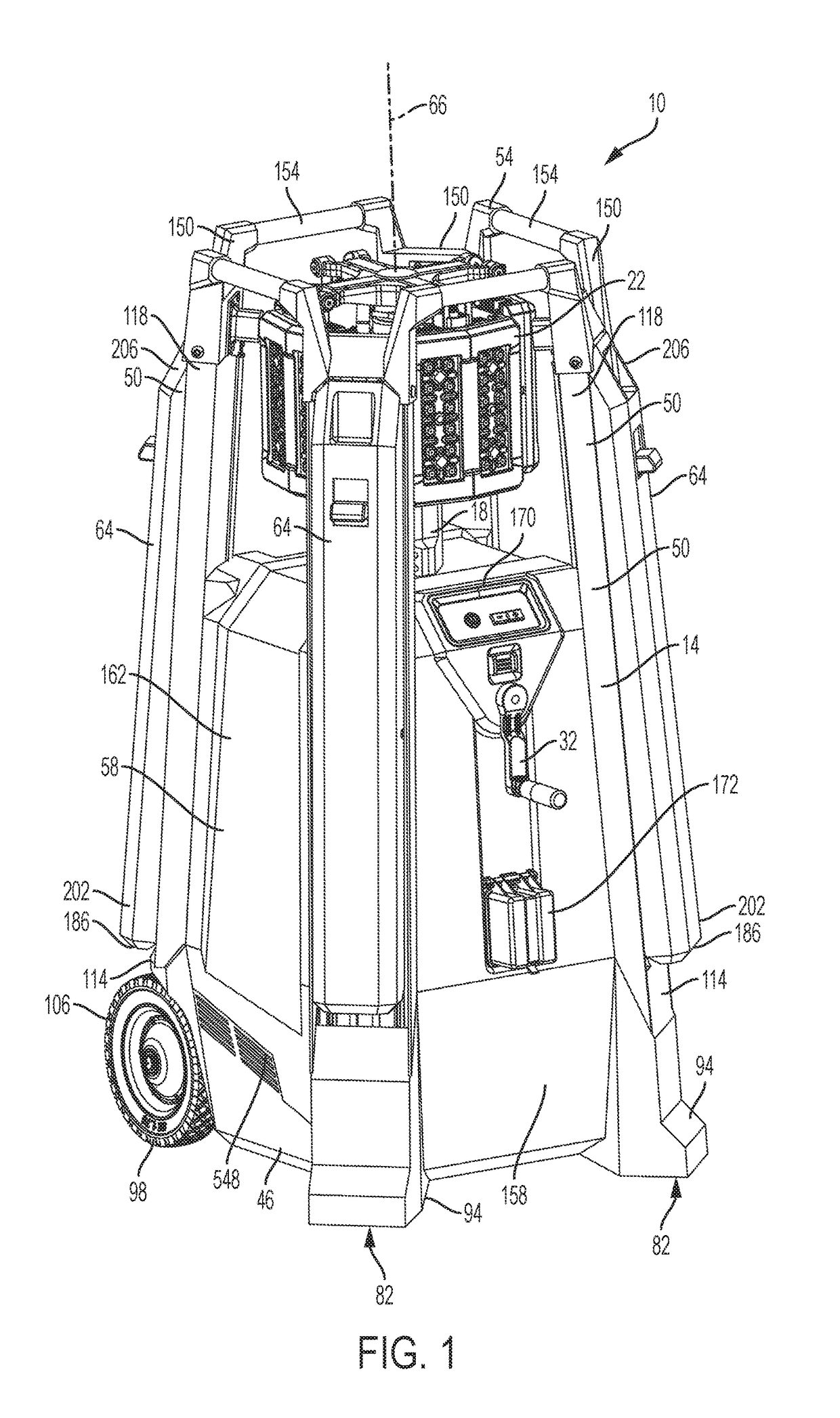
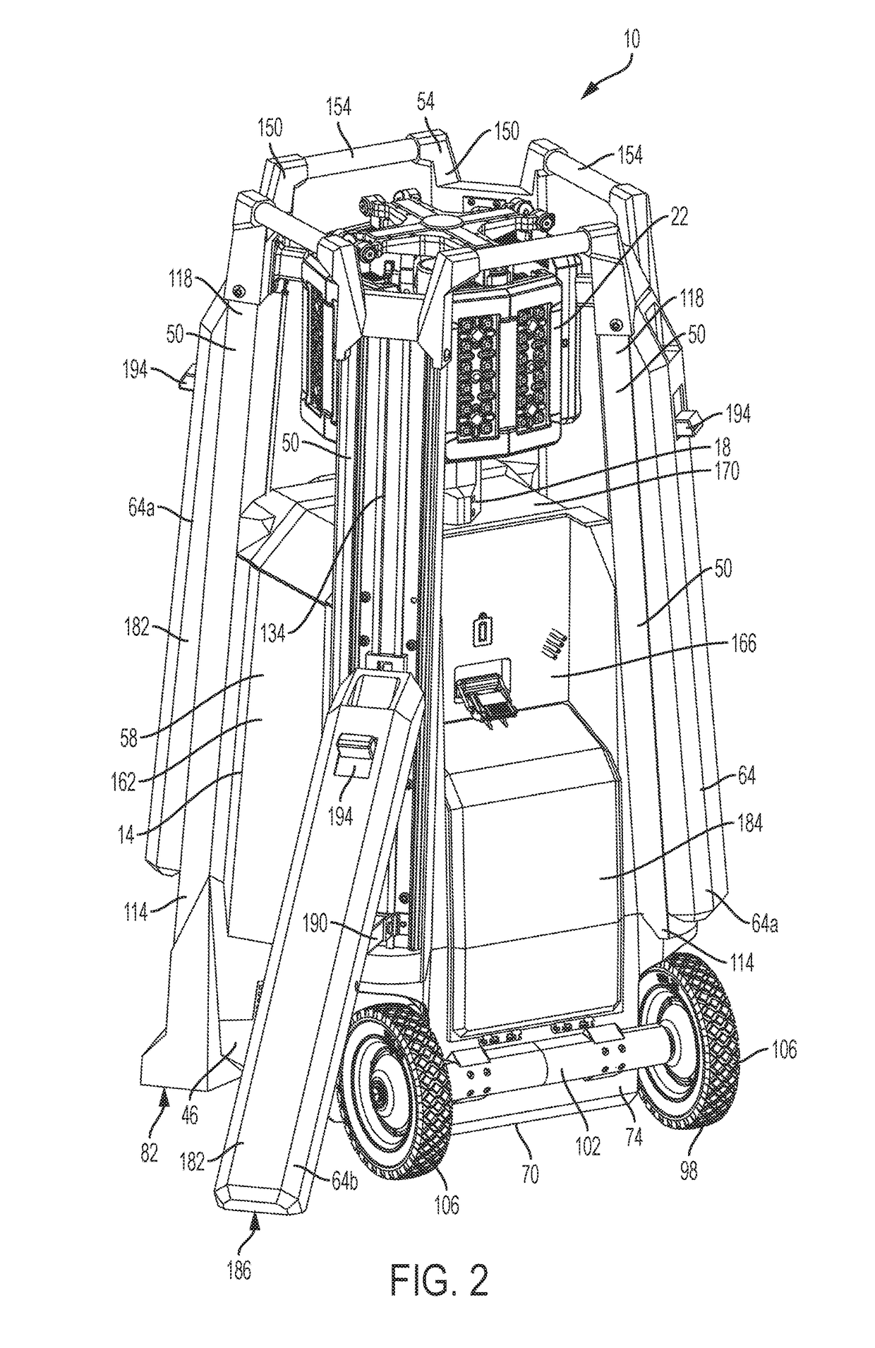
[0061]FIGS. 1-6 illustrate a mobile site light 10 for illuminating a jobsite, such as a construction site, or other large area. The site light 10 includes a body 14, a telescopic arm assembly 18 supported by the body 14, and a light assembly 22 coupled to the telescopic arm assembly 18 and movable relative to the body 14. As shown in FIG. 5, the site light 10 also includes a power system 26 to provide electrical power to the light assembly 22, and a cooling system 30 to regulate the temperature of the power system 26 and the other components of the site light 10.

[0062]Illustrated in FIG. 7, the body 14 of the site light 10 includes a base 46, a plurality of channels 50 coupled to the base 46, a handle assembly 54 coupled to the channels 50 opposite the base 46, and a housing 58 (FIG. 5) supported by the channels 50 to at least partially define a housing volume 62 therein. As shown in FIG. 1, the body 14 also includes one or more leg assemblies 64 coupled thereto and configured to pr...


PUM

PropertyMeasurementUnit
angleaaaaaaaaaa
angleaaaaaaaaaa
lengthaaaaaaaaaa

Abstract

A site light includes a body, an arm coupled to the body having an adjustable arm length, a light assembly coupled to the arm opposite the body, and a drive mechanism with a crank arm rotatable about a first axis. Rotating the crank arm in a first direction causes the arm length to increase. Rotating the crank arm in a second direction causes the arm length to decrease. The drive mechanism is adjustable between a first configuration, where the crank arm can only rotate in the first direction, and a second configuration, where the crank arm can be rotated in the first direction and the second direction.

Description

CROSS-REFERENCE TO RELATED APPLICATIONS[0001]The present application claims priority to U.S. Patent Application No. 62 / 413,742, filed Oct. 27, 2016; U.S. Patent Application No. 62 / 534,009, filed Jul. 18, 2017; and U.S. Patent Application No. 62 / 550,295, filed Aug. 25, 2017. The entire contents of each application are hereby incorporated by reference.FILED OF THE INVENTION[0002]The present disclosure relates to site lights for illuminating a jobsite, such as a construction site and the like.BACKGROUND OF THE INVENTION[0003]Mobile light systems are generally used in construction and other instances where permanent lighting is not readily available. In such instances, current light systems are generally limited in their ability to compensate for the difficulties of working in remote areas such as, for example, uneven terrain, the lack of an external power source, and movement within the site.SUMMARY OF THE INVENTION[0004]In one aspect, the invention provides a site light including a bo...

Claims


Application Information

Patent Timeline
Patent Type & Authority Applications(United States)
IPC IPC(8): F21V21/22F21V23/00F21S9/02F21V17/00F21S8/08F21V29/508F21V29/67F21V17/02H01B7/22B65H75/42B65H75/44
CPCF21V21/22F21V23/001F21S9/02F21V17/007F21S8/085F21V29/508F21V29/67F21V17/02H01B7/226B65H75/42B65H75/4494F21Y2115/10F21V21/06F21W2131/1005F21L14/04
Inventor PROEBER, DAVIDMCINTYRE, ROSSTHURNER, JASON D.VERHAGEN, MICHAEL A.MUECKL, GARETHCORNELL, BRIANHANSEN, DALTON F.SLECK, ANTHONY R.
Owner MILWAUKEE ELECTRIC TOOL CORP
Learn More