Movable imaging device and movable imaging method

a technology of moving imaging and imaging method, which is applied in the field of moving imaging device and movable imaging method, can solve the problems of severe limitation of the place where inspection is performed, and achieve the effect of shortening the time required for the entire inspection and reducing the moving tim

Active Publication Date: 2018-05-03
FUJIFILM CORP
View PDF0 Cites 9 Cited by
  • Summary
  • Abstract
  • Description
  • Claims
  • Application Information

AI Technical Summary

Benefits of technology

[0043]According to the invention, it is possible to shorten the time required for the entire inspection by reducing the moving time of a moving body and the number of times of movement of the moving body and to acquire a high-quality image for inspection, which can satisfy the required inspection accuracy, without requiring a large device.

Problems solved by technology

However, since a large device including the plurality of cameras, the crane truck, the arm, a frame, and the like is required, there is a severe limitation on a place where inspection is performed.

Method used


Image

  • Movable imaging device and movable imaging method
  • Movable imaging device and movable imaging method
  • Movable imaging device and movable imaging method

Examples


modification example 1

[0125]Next, Modification example 1 of the movable imaging device 10 will be described. An imaging control unit 204 of the movable imaging device 10 of this example includes an imaging condition determining unit that determines imaging conditions of the camera 202. Further, the imaging condition determining unit determines the imaging conditions on the basis of the imaging angle that is acquired by the imaging angle acquiring unit 132. For example, the imaging condition determining unit determines a diaphragm value (F-number) on the basis of the imaging angle that is acquired by the imaging angle acquiring unit 132.

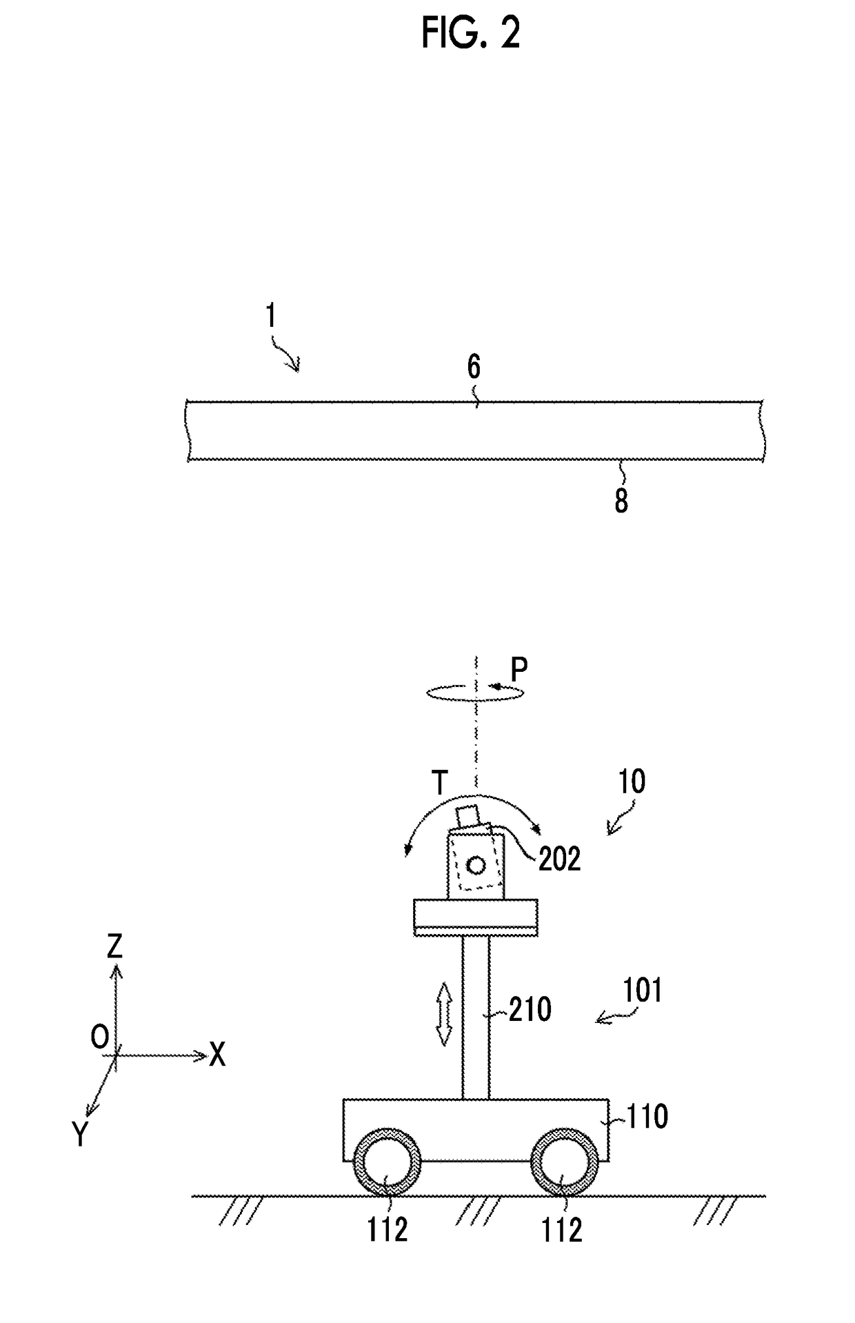
[0126]FIG. 10 is the same cross-sectional view as FIG. 2, and shows a case in which an imaging angle is β. In a case in which the imaging angle is not 90°, that is, in a case in which a camera 202 does not directly face a subject, there is a case where an object to be inspected is not in the depth of field of the camera 202. Accordingly, the imaging condition determining u...

modification example 2

[0131]Next, Modification example 2 of the movable imaging device 10 will be described. A definition calculation unit 128 corrects the definition, which is calculated, on the basis of optical characteristics of an optical system of the camera 202.

[0132]FIG. 11 is a diagram conceptually showing an image 250 for inspection. There is a case where image quality deteriorates at a specific position on the image 250 for inspection in some optical systems. For example, a modulation transfer function (MTF) deteriorates at an end portion of an image for inspection by an optical system being in use, so that image quality deteriorates. Accordingly, as shown in FIG. 11, the definition of an area I is determined as it is by the determination unit 134, the definition of an area II is determined by the determination unit 134 after being multiplied by a coefficient X (=0.8), and the definition of an area III is determined by the determination unit 134 after being multiplied by a coefficient X (=0.6)....

modification example 3

[0134]Next, Modification example 3 of the movable imaging device 10 will be described. The movable imaging device 10 of this example moves while tracking the next imaging area.

[0135]FIG. 12 is a diagram showing the flow of an operation in a case in which the movable imaging device 10 of this example is to move.

[0136]A case in which the determination unit 134 determines that the definition of the image for inspection is lower than the required definition and the movable imaging device 10 moves the moving body 101 as in Step S20 described in FIG. 8 will be described.

[0137]First, the moving body 101 receives a movement command (Step S50). After that, the imaging control unit 204 determines whether or not the second imaging area is caught on the camera 202 before the start of the movement of the moving body 101 (Step S51). If the imaging control unit 204 determines that the second imaging area is not change on the camera 202 (in the case of “NO” in Step S51), the movement of the moving ...


PUM


Abstract

A movable imaging device includes a camera, a moving body, a definition calculation unit that calculates definition of an image for inspection, a determination unit that determines whether the definition is equal to or higher than required definition required for inspection accuracy of an object to be inspected, a pan/tilt control unit that operates a pan/tilt mechanism in a case in which the determination unit determines that the calculated definition is equal to or higher than the required definition, a moving body control unit that moves a moving body in a case in which the pan/tilt mechanism is operated and it is determined that the definition is lower than the required definition, and an imaging control unit that images the object to be inspected by the camera in a case in which it is determined that the definition is equal to or higher than the required definition.

Description

CROSS-REFERENCE TO RELATED APPLICATIONS[0001]The present application is a Continuation of PCT International Application No. PCT / JP2016 / 066237 filed on Jun. 1, 2016 claiming priority under 35 U.S.C § 119(a) to Japanese Patent Application No. 2015-131290 filed on Jun. 30, 2015. Each of the above applications is hereby expressly incorporated by reference, in their entirety, into the present application.BACKGROUND OF THE INVENTION1. Field of the Invention[0002]The present invention relates to a movable imaging device and a movable imaging method, and more particularly, to a movable imaging device and a movable imaging method that image a building structure with a camera including a pan / tilt mechanism to inspect the building structure.2. Description of the Related Art[0003]In recent years, a building structure, such as a bridge, has been imaged by a camera and the taken image of the building structure has been analyzed by an image processing technique, so that the inspection of the build...

Claims


Application Information

Patent Timeline
Patent Type & Authority Applications(United States)
IPC IPC(8): H04N5/232G06T7/00
CPCH04N5/23296H04N5/23203G06T7/0004H04N5/23293G06T2207/30184G03B17/561H04N23/555H04N23/57H04N23/676H04N23/634H04N23/695H04N23/69H04N23/66G03B15/00G03B17/00G03B17/56
Inventor IRIE, FUMINORIWATANABE, MIKIO
Owner FUJIFILM CORP
Why Eureka
Try Eureka