Signal protocol fault detection system and method

a fault detection and signal protocol technology, applied in the direction of program control, testing/monitoring control system, instruments, etc., can solve the problems of sensor(s) incurring one or more faults, sensor(s) may not operate properly, and the system has one or more sensors that may not operate properly

Active Publication Date: 2018-05-10
INFINEON TECH AG
View PDF0 Cites 8 Cited by
  • Summary
  • Abstract
  • Description
  • Claims
  • Application Information

AI Technical Summary

Problems solved by technology

During operation, sensing systems having one or more sensors may improperly operate.
For e

Method used


Image

  • Signal protocol fault detection system and method
  • Signal protocol fault detection system and method
  • Signal protocol fault detection system and method

Examples


Embodiment Construction

[0016]In the following description, numerous specific details are set forth in order to provide a thorough understanding of the embodiments of the present disclosure. However, it will be apparent to those skilled in the art that the embodiments, including structures, systems, and methods, may be practiced without these specific details. The description and representation herein are the common means used by those experienced or skilled in the art to most effectively convey the substance of their work to others skilled in the art. In other instances, well-known methods, procedures, components, and circuitry have not been described in detail to avoid unnecessarily obscuring embodiments of the disclosure.

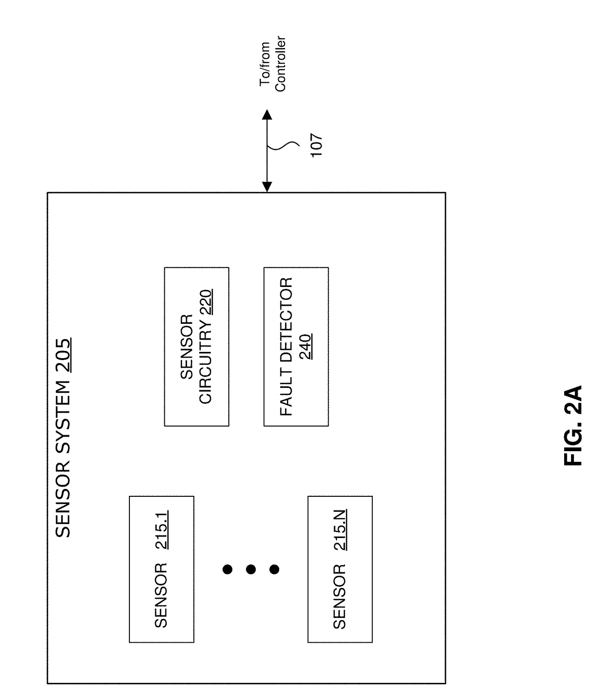
[0017]Embodiments are described with reference to sensing systems having one or more sensors (e.g. magnetoresistive sensors configured to measure, for example, rotational speed and / or direction of a rotating object). The systems can be configured to perform one or more signal processing...


PUM


Abstract

In systems, such as sensor systems, an output signal of the system (e.g. output of the sensor corresponding to a sensed characteristic) can be generated and provided. In response to a detected error, the output signal can be adjusted to generate an error indication signal pulse to indicate that an error has been detected. The output signal can then be adjusted to return to a signal level corresponding to the sensed characteristic. In response to the error being resolved, an error resolution signal pulse can be generated.

Description

CROSS REFERENCE TO RELATED APPLICATIONS[0001]This patent application claims the benefit of U.S. Provisional Patent Application No. 62 / 417,749, filed Nov. 4, 2016, entitled “PWM PROTOCOL WITH 3RD CURRENT LEVEL FOR STANDSTILL AND SAFETY,” which is incorporated herein by reference in its entirety.BACKGROUNDField[0002]Embodiments described herein generally relate to signal processing and fault detection systems and methods, including fault detection signaling systems and methods in sensor systems.Related Art[0003]During operation, sensing systems having one or more sensors may improperly operate. For example, the sensor(s) may incur one or more faults or otherwise fail to operate properly. A control unit, such as a controller, may be unaware of the operational status of the sensor(s), which may comprise the overall operation of the system.BRIEF DESCRIPTION OF THE DRAWINGS / FIGURES[0004]The accompanying drawings, which are incorporated herein and form a part of the specification, illustra...

Claims


Application Information

Patent Timeline
IPC IPC(8): G05B23/02G08C25/02G01S7/28H03M1/00
CPCG05B23/0275G08C25/02G01S7/28H03M1/001G01D18/00G05B19/0425G01R23/005
Inventor HAINZ, SIMONHERMANN, ROBERT
Owner INFINEON TECH AG
Why Eureka
Try Eureka