Vehicular electronics interface module and related methods

a technology of electronic interface and vehicle, applied in the field of vehicle electronics interface modules, can solve the problems of inability of radar devices to always correctly inability of radar devices to report an incorrect patrol speed, and inability to accurately identify the correct ground doppler return, etc., and achieve the effect of higher vehicle speed

Inactive Publication Date: 2005-07-07
DECATUR ELECTRONICS
View PDF23 Cites 102 Cited by
  • Summary
  • Abstract
  • Description
  • Claims
  • Application Information

AI Technical Summary

Benefits of technology

[0023] The camera may be a video camera for taking images, and it may part of a video surveillance system that also stores the images, either in analog or digital form. A second camera interface module may have a second data processor for receiving the translated data from the data processor and for communicating the translated data in a form for displaying the translated data with the images taken by the camera. Preferably, the camera has an adjustable field of view that can be adjusted in a plurality of steps from a wide angle of view to a narrow angle field of view depending upon the speed of the vehicle or a range of speeds of the vehicle. For example, the camera may be adjusted to a wide angle of view for a stationary vehicle and for slow speeds and may be adjusted to a narrower field of view for intermediate speeds and to a still narrower field of view for higher vehicle speeds. A narrower field of view at higher speeds eliminates peripheral information which is likely to be blurred by the speed of the vehicle.

Problems solved by technology

One of the common problems in moving police radar is the inability for the radar device to always correctly identify the correct ground Doppler return.
There are numerous conditions that can occur that may cause the radar device to misinterpret and to report an incorrect patrol speed.
However, these methods are not perfect and patrol speed misidentification remains a problem.
A disadvantage of using this method is that the frequency from the speedometer transducer varies with different vehicle manufacturers.
This calibration problem is compounded if the radar device is switched to a different vehicle, since re-calibration must then be performed again.
Unfortunately, such on-board electronics are designed to, and communicate, on different standards.
These different signaling techniques are generally incompatible with each other because of the utilization of different bus arrangements, baud rates, and the like.
However, when a patrol vehicle is in motion, the peripheral information is frequently blurred by the speed of the vehicle and is generally unusable.

Method used


Image

  • Vehicular electronics interface module and related methods
  • Vehicular electronics interface module and related methods
  • Vehicular electronics interface module and related methods

Examples


Embodiment Construction

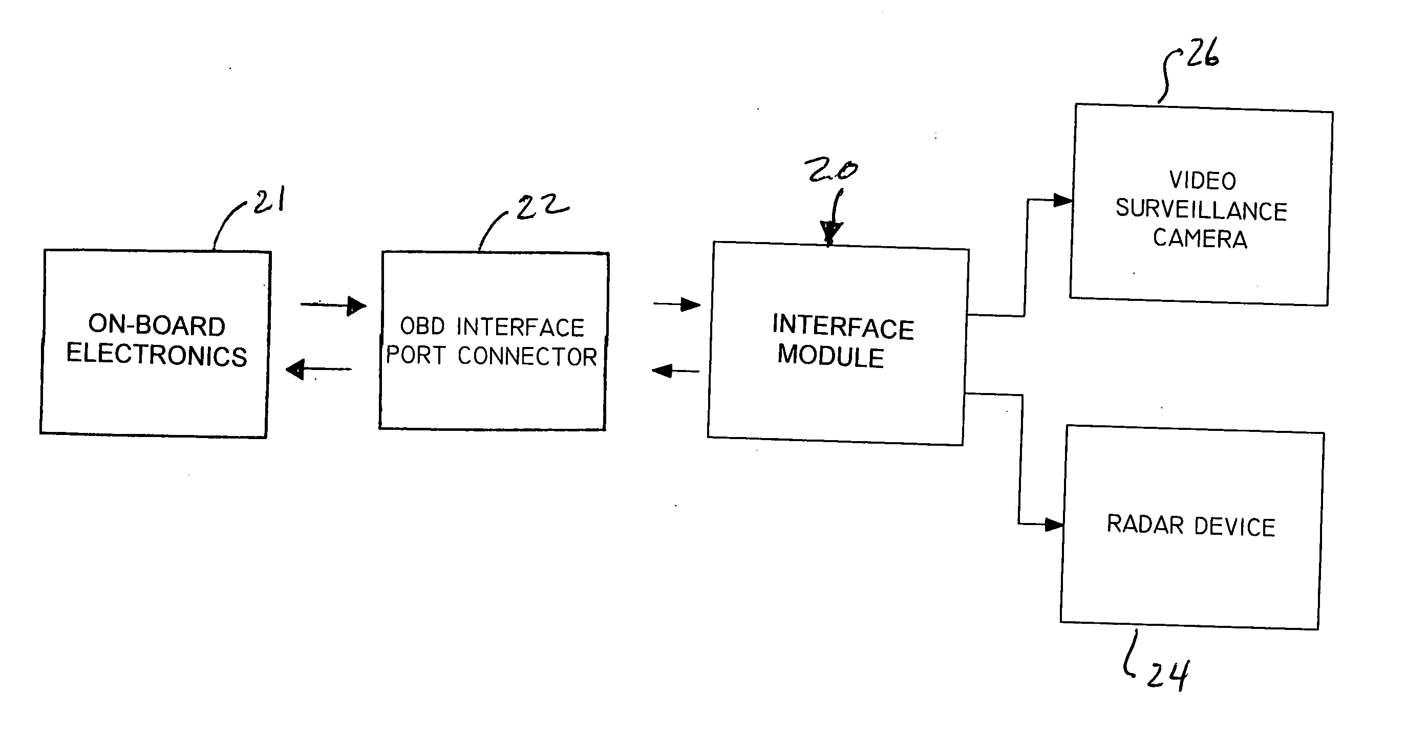
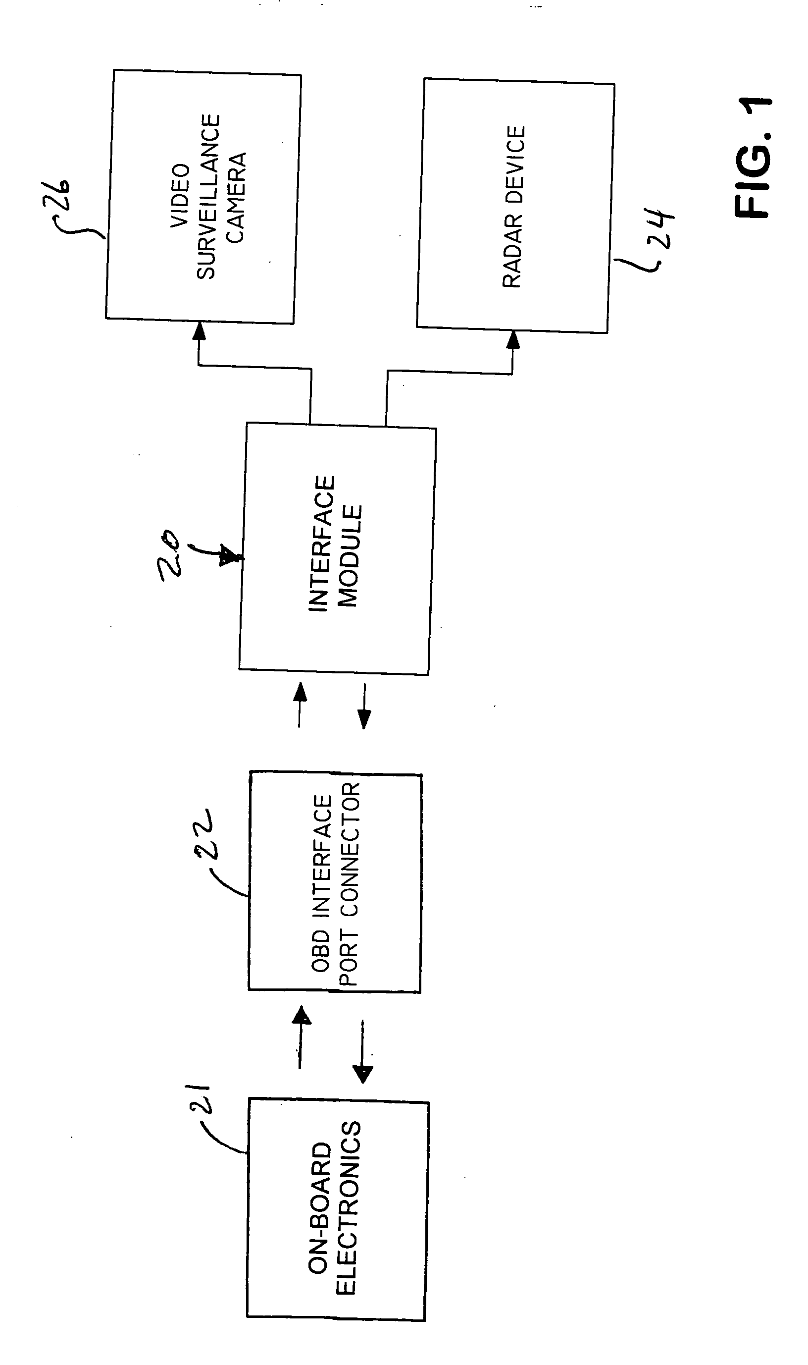
[0037] Referring to the Figures, and particularly to FIG. 1, a radar and video interfacing module, generally designated 20, interfaces between an On-Board Diagnostic (OBD) computer or electronics 21 in a motor vehicle and a radar device 24 and / or a video surveillance system 26 via an OBD interface connector 22, and provides communication between the OBD electronics 21 and the radar device 24 and / or the video surveillance system 26. Such OBD computers have been installed in all vehicles since 1996. The radar device 24 thus receives vehicle speed information from the OBD electronics 21 independent of the make or model of the vehicle. The communication path between the OBD electronics 21 and the radar device 24 is provided by electronic circuitry 70, which is described in detail below with reference to FIG. 4. This circuitry interrogates a plurality of different busses to select and use a bus that is compatible with signaling format the OBD electronics. The radar device 24 then automat...


PUM


Abstract

An interface module for interfacing on-board electronics in a vehicle with a radar device and/or camera. A plurality of data busses are configured for different signaling protocols, such as variable pulse width, pulse width modulated and ISO 9141. A data processor activates the data busses and selects the bus that is most compatible with the on-board electronics. Data is then received and translated to a form compatible with the radar device and/or camera. Typically, the data provided will be vehicle speed information which is used by the radar device to identify the best candidate in the radar Doppler return or is displayed with images taken by the camera. The speed information is also used to control the field of view of the camera, with wider angles of view used for lower speeds. Related methods are also disclosed.

Description

FIELD OF THE INVENTION [0001] This invention generally relates to traffic radar. More particularly, this invention relates to a apparatus for interfacing on-board vehicular electronics with traffic radar and / or video surveillance systems. BACKGROUND OF THE INVENTION [0002] Traffic radar devices are in widespread use to determine the speed of a target vehicle. Such radar devices transmit radar signals which are reflected by the target vehicle. The reflected radar signals are then processed to determine the speed of the target vehicle. These radar devices accurately determine the speed of a target vehicle if the radar device is stationary or if it is in a stationary patrol vehicle. However, if the radar device is in a moving patrol vehicle, the speed of the patrol vehicle must also be taken into account, such as by adjusting or correcting the speed of the target vehicle as determined by the radar device to account for the relative motion of the patrol vehicle. [0003] One of the common...

Claims


Application Information

Patent Timeline
Patent Type & Authority Applications(United States)
IPC IPC(8): G01S7/00G01S13/86
CPCG01S13/867G01S7/003
Inventor CARMICHAEL, STEVE DOUGLASSMITH, KIMBLE JONCOTTLE, TODD J.
Owner DECATUR ELECTRONICS
Why Eureka
Try Eureka