Concrete joint filling kit, method and device

Inactive Publication Date: 2018-05-17
SOLID SOLUTION PROD INC
View PDF0 Cites 0 Cited by
  • Summary
  • Abstract
  • Description
  • Claims
  • Application Information

AI Technical Summary

Benefits of technology

[0017]One of aspects of the present system and method relate to a premeasured unit of part A packaged in a bottle that is also used for pouring premeasured part B and premeasured pigment bags into the bottle containing part A. Part A, Part B and the pigment liquid are mixed together using a special designed mixer. Having the pigment not already in either the part A or B allows flexibility of adding different colors so that that the joint filler can be color matched to the concrete with the joint to be filled. Secondly, for large size bottle, a gun is used to compress and restrain the bottle as the user dispenses the joint filler into the concrete joint.
[0018]Disclosed is a system for filling concrete control/saw-cut and cold/expansion joints. The system consists of three liquid elements, namely, an A-side portion, a B-side portion, which, when combined, create the liquid compound, and an optional liquid pigment, which allows a user to match the color of the compound formed by the A and B-side portions to the color of the concrete surrounding a joint being filled. When the A-side and B-side portions are mixed, they from a hybrid aliphatic polyurea compound which hardens in a short time. The disclosed hybrid aliphatic polyurea compound is suited to both indoor and outdoor use. Particularly in regard to outdoor use, the compound offers about 600% elongation and hardens to about 80 durometer. The compound may also be UV-tolerant, which is one contributing factor to the compound's high color stability. The A-side portion may come in a mixing contai

Problems solved by technology

Unfortunately, once Part A and Part B are mixed with each other, they set very fast so that they have to be applied to the joint quickly before they set.
The quick setting nature of Parts A and B after being mixed limits the methods and apparatus for applying the joint filler materials to the joint.
The method and apparatus for filling/applying fast setting joint fillers in concrete joints are limited to using a plural metering electric pump or with a dual cartridge loaded in a dual cartridge gun.
The plural metering pumps are expensive and require a thorough cleaning af

Method used


Image

  • Concrete joint filling kit, method and device
  • Concrete joint filling kit, method and device
  • Concrete joint filling kit, method and device

Examples


Embodiment Construction

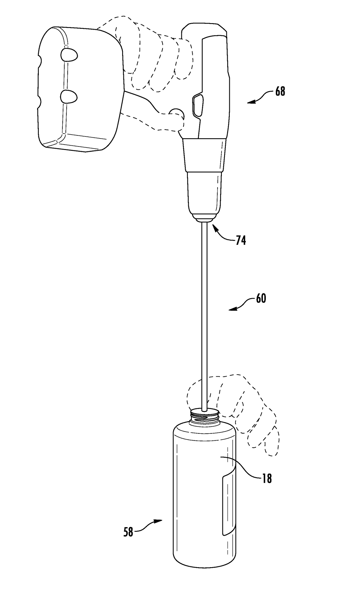
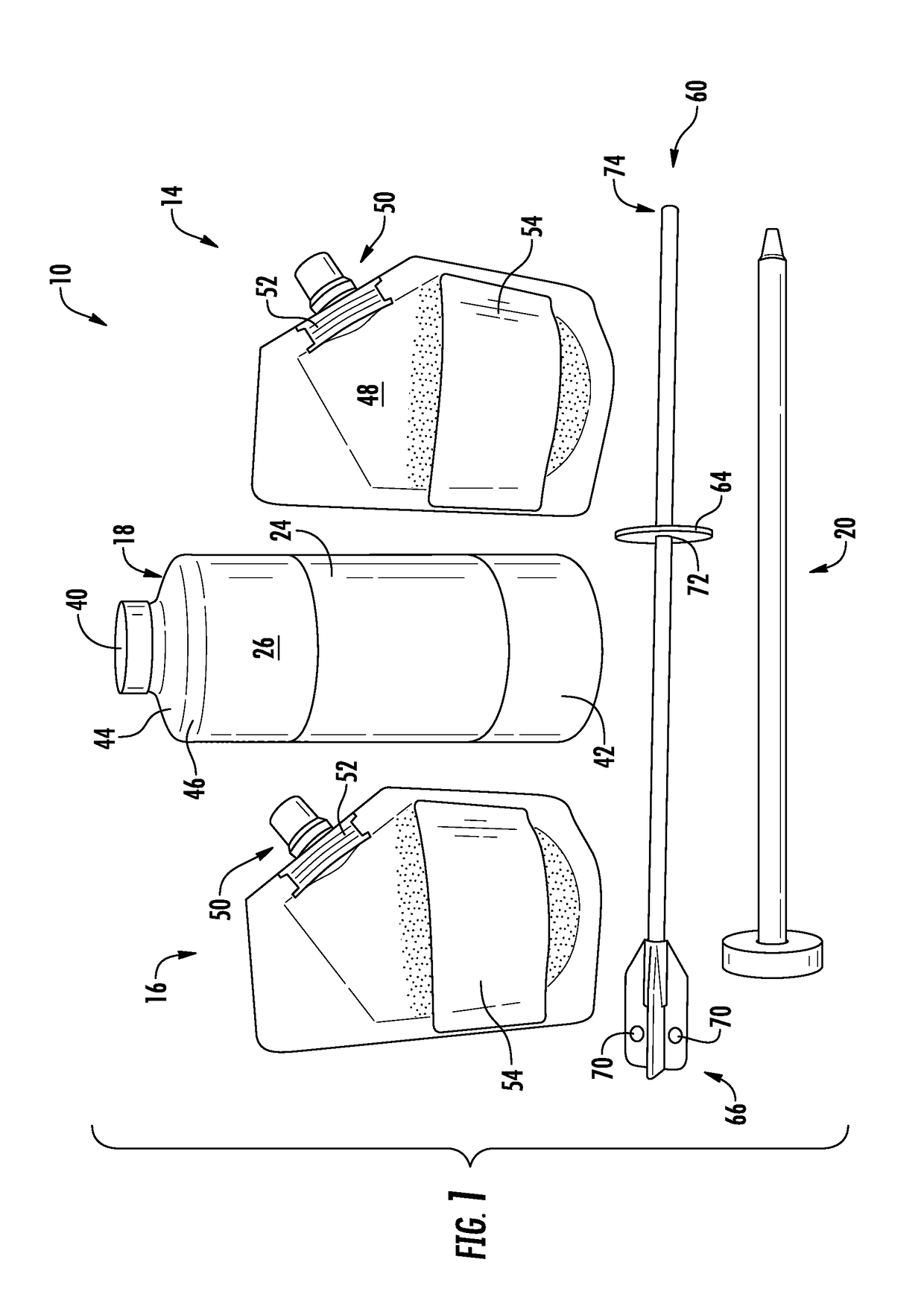
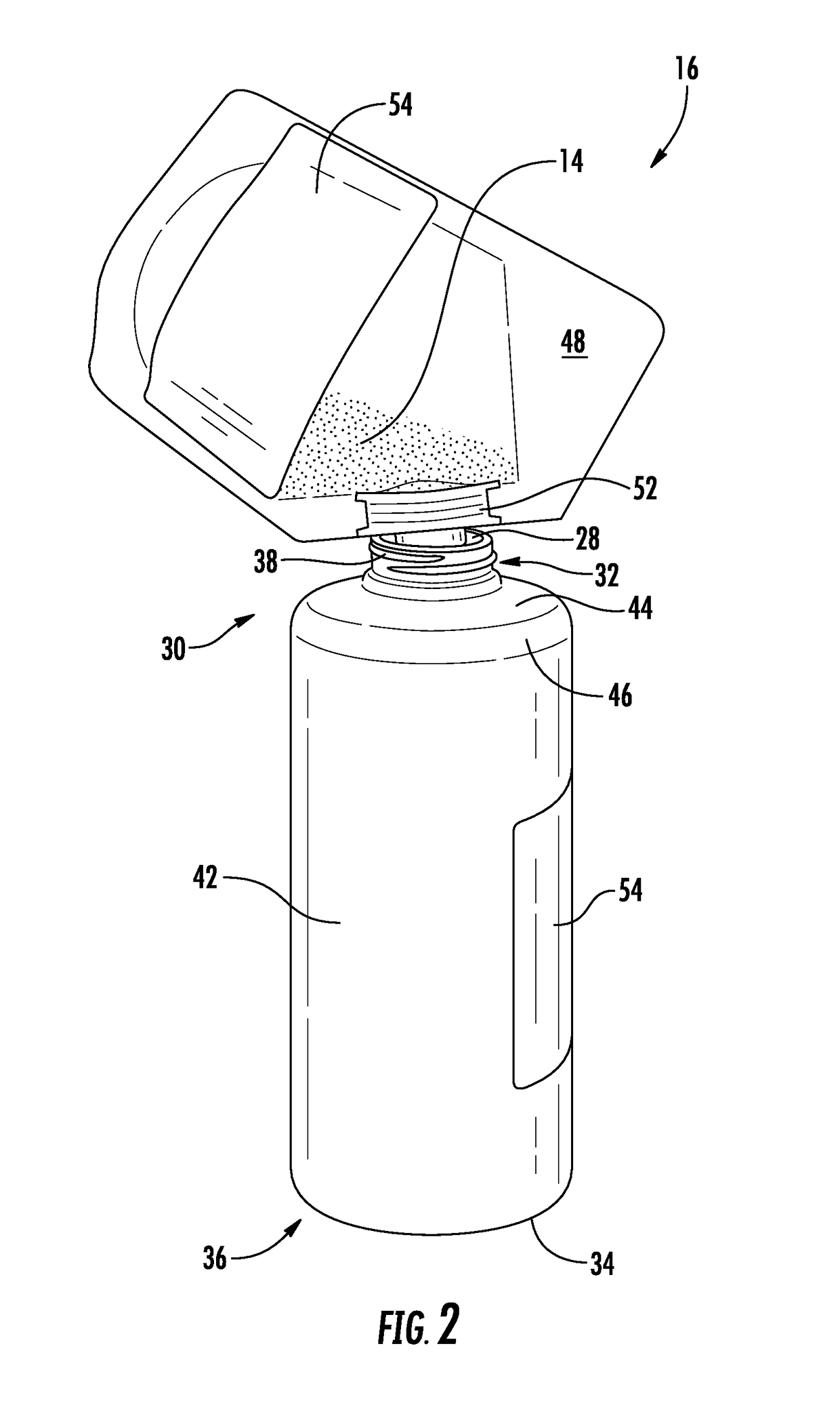
[0050]Disclosed is a system for filling joints in concrete surfaces. The system 10 may consist of three liquid elements, namely, an A-side portion 12, which includes a portion of the liquid compound, a B-side portion 14, which includes another portion of the liquid compound, and an optional liquid pigment 16, which allows a user to match the color of the compound formed by the A and B-side portions 12, 14 to the color of the concrete surrounding a joint being filled. The A-side portion may come in a mixing container 18 into which both the B-side portion and the liquid pigment may be added. The mixing container is sized to match typical job sizes, which prevents a requirement to store excess inventory. The A-side, B-side and pigment portions have an extended shelf life when compared to typical polyurea cartridges, and unlike known polyuria cartridges, by separating the pigment portion from the A-side and B-side portions, the user can select one of a plurality of pigment portions to m...


PUM


Abstract

A system and method for filling joints in concrete. The system includes an A-side joint filler compound portion, a B-side joint filler compound portion, and a liquid pigment portion, which are mixed together in a mixing container initially containing only the A-side joint filler compound portion. The portions are mixed using a mixing rod. An elongate nozzle is then attached to the mixing container, and the mixing container added to an application gun for application to the joint.

Description

CROSS-REFERENCE TO RELATED APPLICATIONS[0001]This application is a continuation in part of U.S. patent application Ser. No. 15 / 251,644, filed on Aug. 30, 2016, the entire content of which is expressly incorporated herein by reference.STATEMENT RE: FEDERALLY SPONSORED RESEARCH / DEVELOPMENT[0002]Not ApplicableBACKGROUND[0003]The system and method herein relates to a system and method for filling “control” or “saw-cut” joints and “cold” or “expansion” joints in concrete floors.[0004]In placement of concrete floors there are normally two types of joints. Cold or expansion joint result when a section of a concrete floor is placed / pour by a previous section of concrete floor that was placed earlier that has hardened. Control or saw-cut joints are made when a large section of floor is placed. The control or saw-cut joints control cracking in large sections or slabs of concrete floor. The control or saw-cut joints are made early on in the placement of concrete floor, specifically, after the ...

Claims


Application Information

Patent Timeline
IPC IPC(8): B05C17/005B05D1/26
CPCB05C17/0052B05D1/265B05C17/00503E04F21/165B05C17/01B05C17/00583B65D81/00B05C17/00513
Inventor BOWERS, BRIAN
Owner SOLID SOLUTION PROD INC
Why Eureka
Try Eureka