Electric optical cable

A technology of optical cable and electric power, which is applied in the direction of light guide, optics, optical components, etc., can solve the problems of difficulty in the thickness of the marking strip of the sheath of the hanging wire, increase the weight and cost of the optical cable, and the unsatisfactory performance of the optical cable sheath, etc., to achieve convenient thickness control and product quality The effect of fast production speed and light weight

Inactive Publication Date: 2016-06-15
SUZHOU HIGH & SPECIALITY INFORMATION TECH CO LTD
View PDF8 Cites 0 Cited by
  • Summary
  • Abstract
  • Description
  • Claims
  • Application Information

AI Technical Summary

Problems solved by technology

The above-mentioned document does disclose the marking strip for optical cable identification, but it has the following common defects: (1) using stranded steel wire as the reinforcement part of the suspension wire to realize self-support, although it has achieved the function of greater bearing capacity, but , the sheath outside the stranded steel wire is extremely rough, and the performance of the sheath of the optical cable is extremely unsatisfactory; to achieve smoothness, the thickness of the sheath must be greatly increased, which increases the weight and cost of the optical cable and shortens the span of the optical cable.
(2) According to the defect of (1) above, it is difficult to control the thickness of the marking strip on the suspension wire sheath, so the quality of the product is extremely unstable and the production speed is quite slow
In addition, the color of the identification strips in the prior art is generally unstable. In Southeast Asia, after one year of overhead cable laying, the identification strips have faded to varying degrees, which affects the accurate use of the identification.

Method used


Image

  • Electric optical cable
  • Electric optical cable
  • Electric optical cable

Examples


Embodiment 1

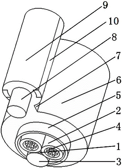
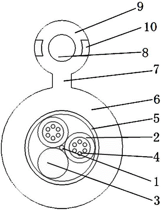
[0033] please see figure 1 and figure 2 , a power optical cable, which is composed of a cable core, an outer sheath 6 covering the cable core, a reinforcement element 8, a suspension wire sheath 9 covering the reinforcement element, and a rib 7 connecting the suspension wire sheath and the outer sheath The cable core is composed of a central central reinforcement 1, a filling rope 3 outside the central reinforcement, two loose tubes 2, and a protective layer 5 covering the filling rope and the loose tube; each loose There are six optical fibers 4 in the casing; the characteristic is that the reinforcing element is a single phosphating steel wire, two marking strips 10 are symmetrically arranged on the suspension wire sheath, and the suspension wire sheath, outer sheath, and ribs are integrally formed And it is the same material; the filling rope and multiple loose sleeves are twisted around the central reinforcement; the thickness of the marking strip is 0.5mm; the material ...

Embodiment 2

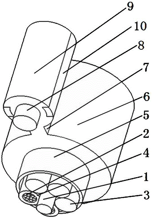
[0035] please see image 3 and Figure 4 , and refer to figure 1 and figure 2, a power optical cable, basically the same as the implementation example 1, the difference is that there are three filling ropes 3, and two loose tubes 2; the marking strip is made of the following raw materials by weight: the same material as the outer sheath 95 parts, 3 parts of commercially available polyethylene color masterbatch, 8 parts of titanium dioxide, 0.8 part of antioxidant of commercially available model 1010, 3 parts of natural paraffin.

Embodiment 3

[0037] please see Figure 5 , and refer to image 3 and Figure 4 , a power optical cable, basically the same as the implementation example 2, the difference is that there are two filling ropes 3, and three loose tubes 2; the marking strip is made of the following raw materials by weight: the same material as the outer sheath 93 parts, 1.5 parts of commercially available polyethylene color masterbatch, 7 parts of titanium dioxide, 0.6 part of anti-oxidant of commercially available model 1010, 2 parts of natural paraffin.


PUM


Abstract

The invention relates to the technical field of cables, in particular to an electric optical cable. The electric optical cable comprises a cable core, an outer sheath covering the cable core, a reinforcement element made of a single steel wire or a glass fiber reinforced plastic, a suspension wire protective layer covering the reinforcement element, and a rib for connecting the suspension wire protective layer with the outer sheath, wherein the cable core is composed of a central reinforcement part positioned in the center, a plurality of loose tubes positioned outside the central reinforcement part, and a protective layer covering the loose tubes; at least one optical fiber is arranged in each loose tube; two marking strips are symmetrically arranged on the suspension wire protective layer; the suspension wire protective layer, the outer sheath and the rib made from the same materials are integrally formed; and the marking strips are made from special materials. The electric optical cable has the following main benefits: the thickness of the suspension wire protective layer is more convenient to control; the suspension wire protective layer is smoother and rounder; a product is higher in production speed and higher in qualification rate; the optical cable is smaller in self weight and wider in suitable span; and the marking strips are more stable in color.

Description

[0001] This application is a divisional application for an invention patent named: self-supporting optical cable with identification strip, application date: January 26, 2014, and application number: 201410036276.5. technical field [0002] The invention relates to the technical field of cables, in particular to an electric power optical cable. Background technique [0003] A type of power optical cable is mostly used for aerial laying. Due to its excellent load-bearing performance, the laying of the cable can be realized without additional steel strands for support. Usually, the cable is fixed on the clamp at the tower. That is, it can be placed freely between adjacent towers. However, with the rapid development of the communication industry, the number of cables between poles and towers increases sharply, which brings great trouble to maintenance because it is not easy to distinguish. For this reason, a large amount of researches have been carried out at home and abroad. ...

Claims


Application Information

Patent Timeline
Patent Type & Authority Applications(China)
IPC IPC(8): G02B6/44
CPCG02B6/4429G02B6/4432G02B6/4434G02B6/44384
Inventor 赵建荣
Owner SUZHOU HIGH & SPECIALITY INFORMATION TECH CO LTD
Why Eureka
Try Eureka