Large part injection mold apparatus and process

a technology of injection mold and large parts, applied in the field of large part injection mold apparatus and process, can solve the problems of corresponding warpage and high density local, and achieve the effects of effective filling and packing large parts, reducing flow and pressure, and reducing packing pressur

Active Publication Date: 2018-05-17
SYNVENTIVE MOLDING SOLUTIONS INC
View PDF4 Cites 0 Cited by
  • Summary
  • Abstract
  • Description
  • Claims
  • Application Information

AI Technical Summary

Benefits of technology

[0004]A variety of large plastic parts are produced today. These include automotive bumper skins, interior door panels, TV screen bezels and back covers as well as some smaller parts such as computer laptop covers and automotive B pillar trim parts. Larger parts have longer flow paths and a thicker wall can be used to ensure the part can be fully filled. To reduce the weight of a part and maintain a reasonably thin wall section on very large parts it becomes necessary to have more than 1 gate. Multiple gates create multiple flows of plastic in the tool. These flows meet and join as weld lines which are usually an unacceptable cosmetic and / or functional defect. To avoid these defects, current practices often use a sequential valve gate (SVG) system where the gates are opened in sequence to produce one flow of plastic. The opening of successive gates can create disturbances in the flow causing a variety of defects. For this writing, I will focus on how the hold pressure and time is applied to control the packing of large parts.SUMMARY OF THE INVENTION
[0006]With the advent of advanced technology such as gate valve pin position and velocity control, other techniques can be used to more effectively fill and pack large parts. For a typical SVG system such as shown in FIG. 1, again the first gate associated with a centrally located nozzle N1 is opened to either a partially closed position or fully open position to fill the first section 300 of the part that is formed in the cavity 300 of the mold. Then the second gate(s) associated with downstream located nozzles n2, n3 are opened to fill the next section(s). At that point the first nozzle n1 gate valve pin p1 can be either held in an initially selected partially closed position or moved from an initially selected fully open position to a partially closed position for the remainder of the injection cycle to reduce the flow and pressure provided to the first section(s) 302 of the part that is formed in cavity 300. Then as the third gate(s) associated with the nozzles n4, n5 are opened the second gate(s) associated with nozzles n2, n3 are partially closed. Using this process allows the packing of each section 302, 304 immediately after filling. This process is called Progressive Fill.
[0007]With this technique the packing in each section 302, 304 will be sooner in the process. The wall section flow path will be thicker and more molten or active allowing a lower packing pressure. This can eliminate over packing and actually reduce the density of the part resulting in a lighter part with less plastic consumption and reduced warpage. It also can eliminate cosmetic defects caused by sink disturbing the plastic skin contact with the tool surfaces.

Problems solved by technology

The reopening of the gates can be a significant time after first fill so the wall of the part is mostly frozen which requires a higher hold pressure and longer hold time to ensure the sink is fully packed out.
The higher pressure can again lead to over packing creating a higher density locally in the part and the corresponding warpage.

Method used


Image

  • Large part injection mold apparatus and process
  • Large part injection mold apparatus and process
  • Large part injection mold apparatus and process

Examples


Embodiment Construction

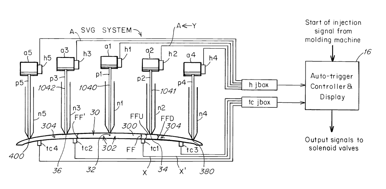
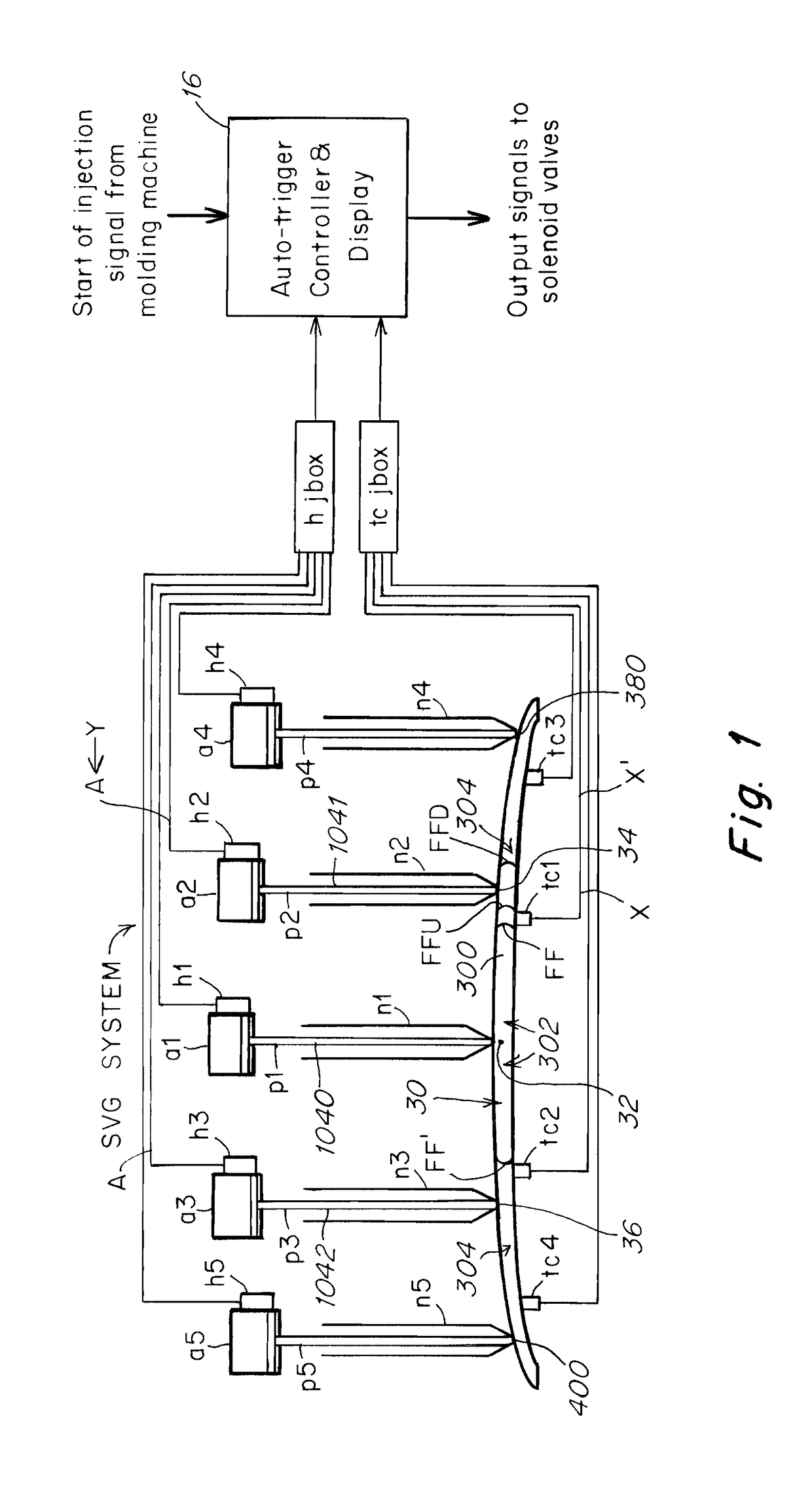
[0077]FIG. 1 shows an injection molding system comprised of a mold having a large cavity 300 that is fed by multiple nozzles n1-n5 each having a controller controlled valve pin p1-p5. At the beginning of an injection cycle all valve pins p1-p5 are all disposed in a gate closed, GC, FIGS. 3A, 4A, position. When the cycle begins a selected nozzle n1 and valve pin p1 is opened first while the others remain closed until triggered to open at a later time. The n1 nozzle and associated pin p1 are selected to withdraw to open the associated gate first because the nozzle n1 has a gate that is disposed at the center of the cavity 300 with the other nozzles N2-N5 having gates that are disposed at positions downstream of the gate of nozzle n1.

[0078]In the embodiment shown temperature sensors tc1-tc4 are used to effect an automatic triggering of the gates to open. Other sensors such as pressure sensors that detect a fluid property in the cavity 300 could alternatively be used. The temperature se...


PUM

PropertyMeasurementUnit
lengthaaaaaaaaaa
instruction timeaaaaaaaaaa
distanceaaaaaaaaaa

Abstract

A method of performing an injection cycle having a duration comprising:beginning the injection cycle with the valve pins associated with two or more nozzles in a gate closed position,selecting a first one of the two or more nozzles and controllably driving its associated valve pin from the gate closed position to a selected first axial upstream position,upon downstream flow of the injection fluid through a cavity the preselected distance, controllably driving the valve pin associated with the other of the two or more nozzles to a selected second axial position upstream,holding or controllably driving the valve pin associated with the first one of the two or more nozzles in or to one or more reduced flow axial upstream positions that are partially closed.

Description

RELATED APPLICATIONS[0001]This application is a continuation of and claims the benefit of priority to PCT / US17 / 061332 filed Nov. 13, 2017 which in turn claims the benefit of priority to U.S. Provisional Application No. 62 / 421,674 filed Nov. 14, 2016 the disclosures of both of which are incorporated by reference as if fully set forth in their entirety herein.[0002]Injection molding is a fairly mature industry. The production of plastic parts is commonplace for almost all sectors of the manufacturing industry. A basic injection molding tool involves a core, a cavity and an entry point for the plastic to enter the cavity. The entry point is typically called the gate. The tool is installed in an injection molding machine (IMM) which opens, closes, and clamps the tool and ejects the part. It also melts or plasticizes the plastic material and injects it into the tool at high pressure and velocity. For many parts it is critical that the plastic is injected at high velocity. As the plastic ...

Claims


Application Information

Patent Timeline
Patent Type & Authority Applications(United States)
IPC IPC(8): B29C45/76B29C45/22B29C45/23B29C45/77
CPCB29C45/7613B29C45/22B29C45/231B29C45/77B29C2945/76545B29C2945/76688B29C2945/76939B29C2045/279
Inventor HENDERSON, WILLIAMFENG, LINGDOVEY, ANDREW
Owner SYNVENTIVE MOLDING SOLUTIONS INC
Why Eureka
Try Eureka