Tire
a technology of patterned sections and linings, applied in the field of tires, can solve problems such as uniform patterned sections, and achieve the effect of enhancing visibility and raising the uniformity of patterned sections
- Summary
- Abstract
- Description
- Claims
- Application Information
AI Technical Summary
Benefits of technology
Problems solved by technology
Method used
Image

Examples
first exemplary embodiment
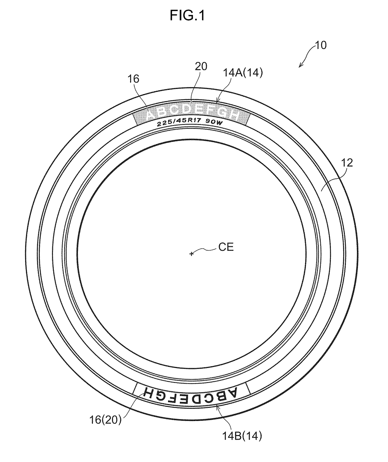
[0078]Explanation follows regarding a first exemplary embodiment of the present invention, with reference to the drawings. FIG. 1 is a side view illustrating a tire 10 according to the present exemplary embodiment. In the present exemplary embodiment, a tire circumferential direction is indicated by C, and a tire radial direction is indicated by R.
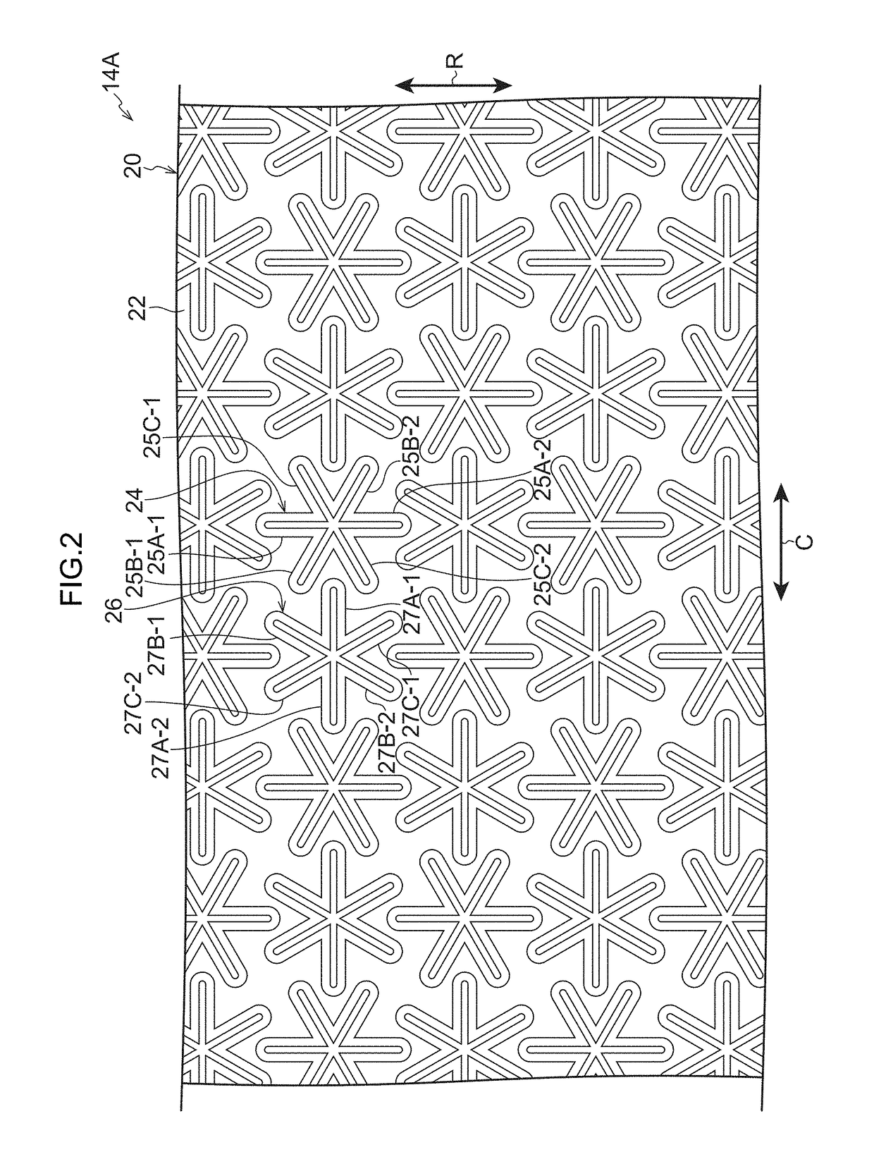
[0079]A tire side portion 12 of the tire 10 is formed with designs 14. The designs 14 are configured in belt shaped circular arcs, and are formed at two locations at symmetrical positions on either side of a tire center axis CE (see FIG. 1). A pattern region 20 and a text region 16 are arranged within the design 14. The text region 16 displays text, such as “ABCDEFGH”, displayed in a smooth plane. In the design 14A on the upper side of the page in FIG. 1, the pattern region 20 configures a type of decorative strip at locations that are not part of the text region 16 of the design 14A, and is formed so as to surround the text region 16. On ...
second exemplary embodiment
[0102]Next, explanation follows regarding a second exemplary embodiment of the present invention. In the present exemplary embodiment, portions similar to those of the first exemplary embodiment are allocated the same reference numerals, and detailed explanation thereof is omitted.
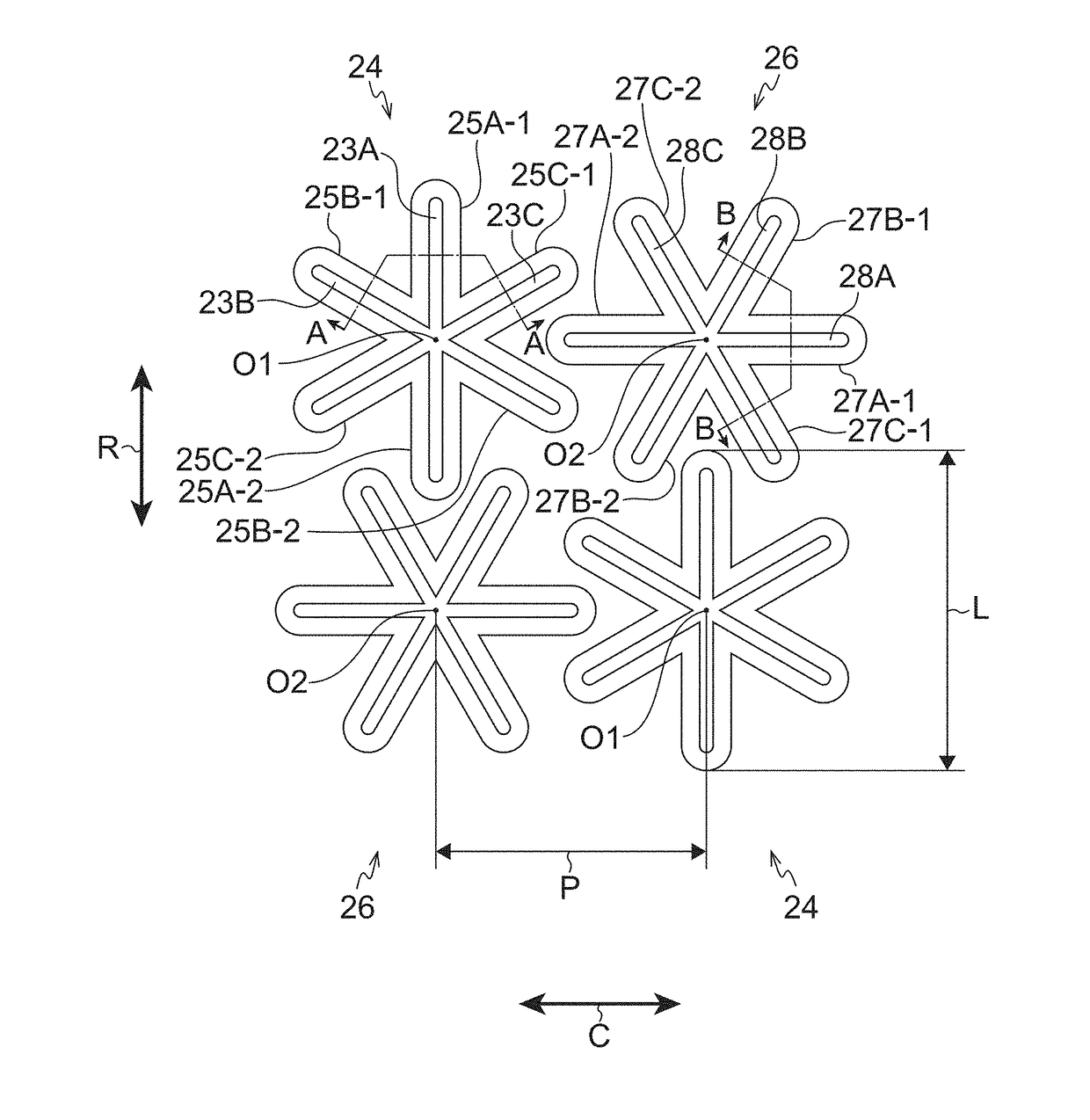
[0103]As illustrated in FIG. 8, the main difference in a tire 10 of the present exemplary embodiment is that in the first asterisk projection 24 and the second asterisk projection 26 of the first exemplary embodiment, an extension length L2 from the leading end of the second extension portion 25B-1 to the leading end of the second extension portion 25B-2, an extension length L2 from the leading end of the second extension portion 27B-1 to the leading end of the second extension portion 27B-2, an extension length L2 from the leading end of the third extension portion 25C-1 to the leading end of the third extension portion 25C-2, and an extension length L2 from the leading end of the third extension portion ...
third exemplary embodiment
[0106]In a tire 10 of the present exemplary embodiment, as illustrated in FIG. 10, the third extension portion 25C-1 of the first asterisk projection 24 of the first exemplary embodiment is curved so as to approach the leading end of the third extension portion 25C-2 of another, adjacent first asterisk projection 24. As illustrated in FIG. 11, the extension length of the third extension portion 25C-1 is longer than that of the other extension portions. Moreover, in the tire 10 of the present exemplary embodiment, the second extension portion 27B-1 of the second asterisk projection 26 of the first exemplary embodiment is curved so as to approach the leading end of the second extension portion 27B-2 of another, adjacent second asterisk projection 26. The extension length of the second extension portion 27B-1 is longer than that of the other extension portions.
[0107]In a pattern region 20-3 of the present exemplary embodiment, the third extension portion 25C-1 and the second extension ...
PUM
 Abstract
Description
Claims
Application Information