
Intake apparatus for engine

a technology for a pump and an engine, which is applied in the direction of machines/engines, combustion air/fuel air treatment, and other domestic objects, can solve the problems of increasing the production cost of a vehicle and the number of work processes, and achieve the effect of strengthening a circular flow

Active Publication Date: 2018-05-24
HYUNDAI KEFICO CORP
View PDF35 Cites 6 Cited by
  • Summary
  • Abstract
  • Description
  • Claims
  • Application Information

AI Technical Summary

Benefits of technology

The present invention is a device that helps engines have a stronger flow of air.

Problems solved by technology

Therefore, the production cost of a vehicle increases, and the number of work processes increase.

Method used


Image

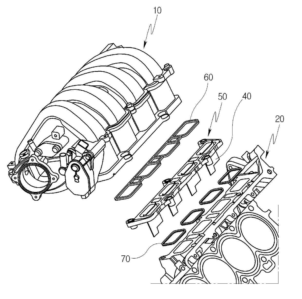
  • Intake apparatus for engine
  • Intake apparatus for engine
  • Intake apparatus for engine

Examples


Embodiment Construction

[0026]Terms or words used hereinafter should not be construed as having common or dictionary meanings, but should be construed as having meanings and concepts that comply with the technical spirit of the present disclosure on the basis of the principle that the inventor may appropriately define the concepts of the terms in order to best describe his or her disclosure. Accordingly, the following description and drawings illustrate exemplary embodiments of the present disclosure and do not fully represent the scope of the present disclosure. It would be understood by one of ordinary skill in the art that a variety of equivalents and modifications of the embodiments exist.

[0027]In the drawings, the width, length, thickness, etc. of each element may have been enlarged for convenience. Furthermore, when it is described that one element is disposed ‘over’ or ‘on’ the other element, one element may be disposed ‘right over’ or ‘right on’ the other element or a third element may be disposed ...


PUM

PropertyMeasurementUnit
shapeaaaaaaaaaa
combustion speedaaaaaaaaaa
combustion reliabilityaaaaaaaaaa

Abstract

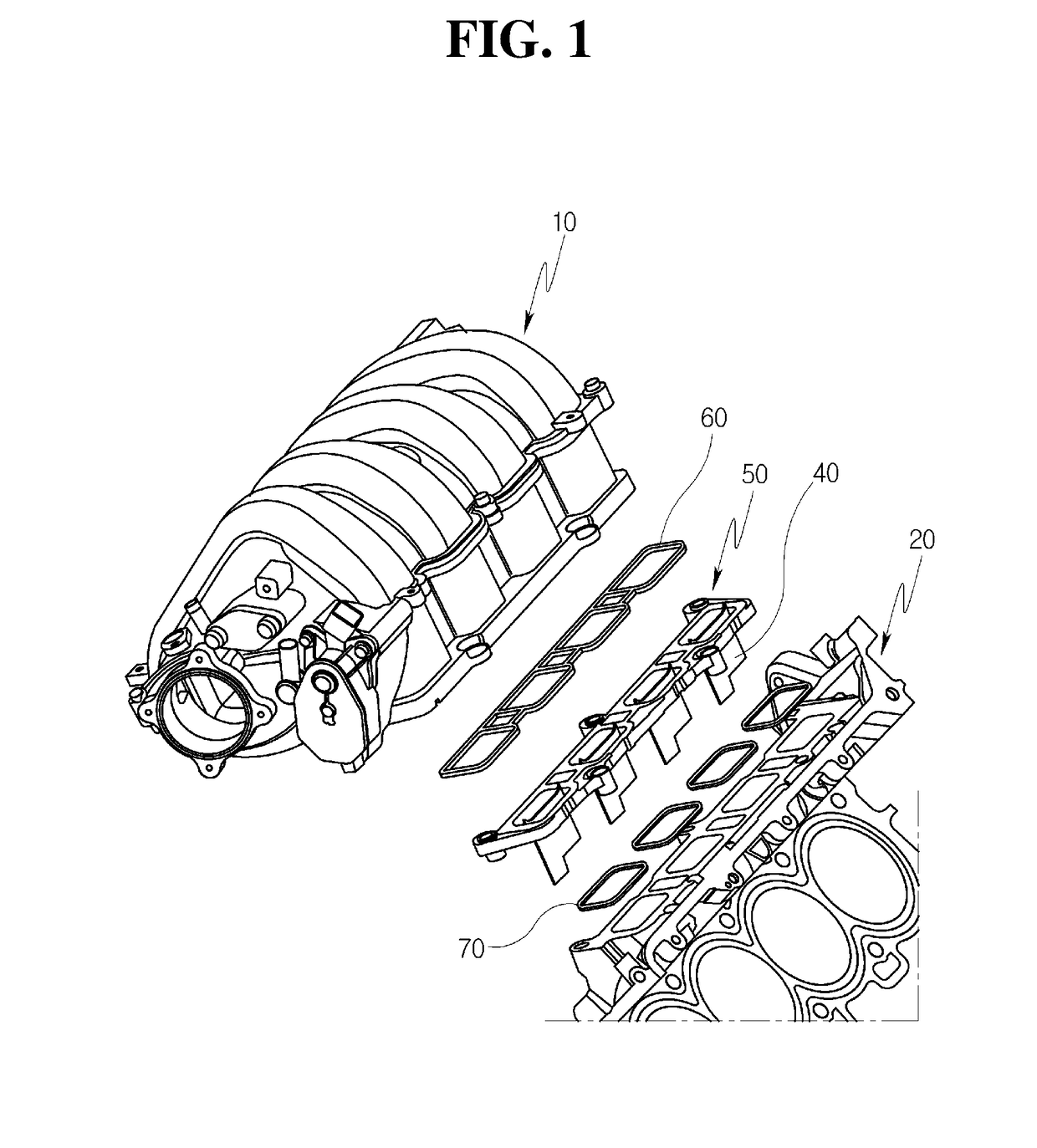
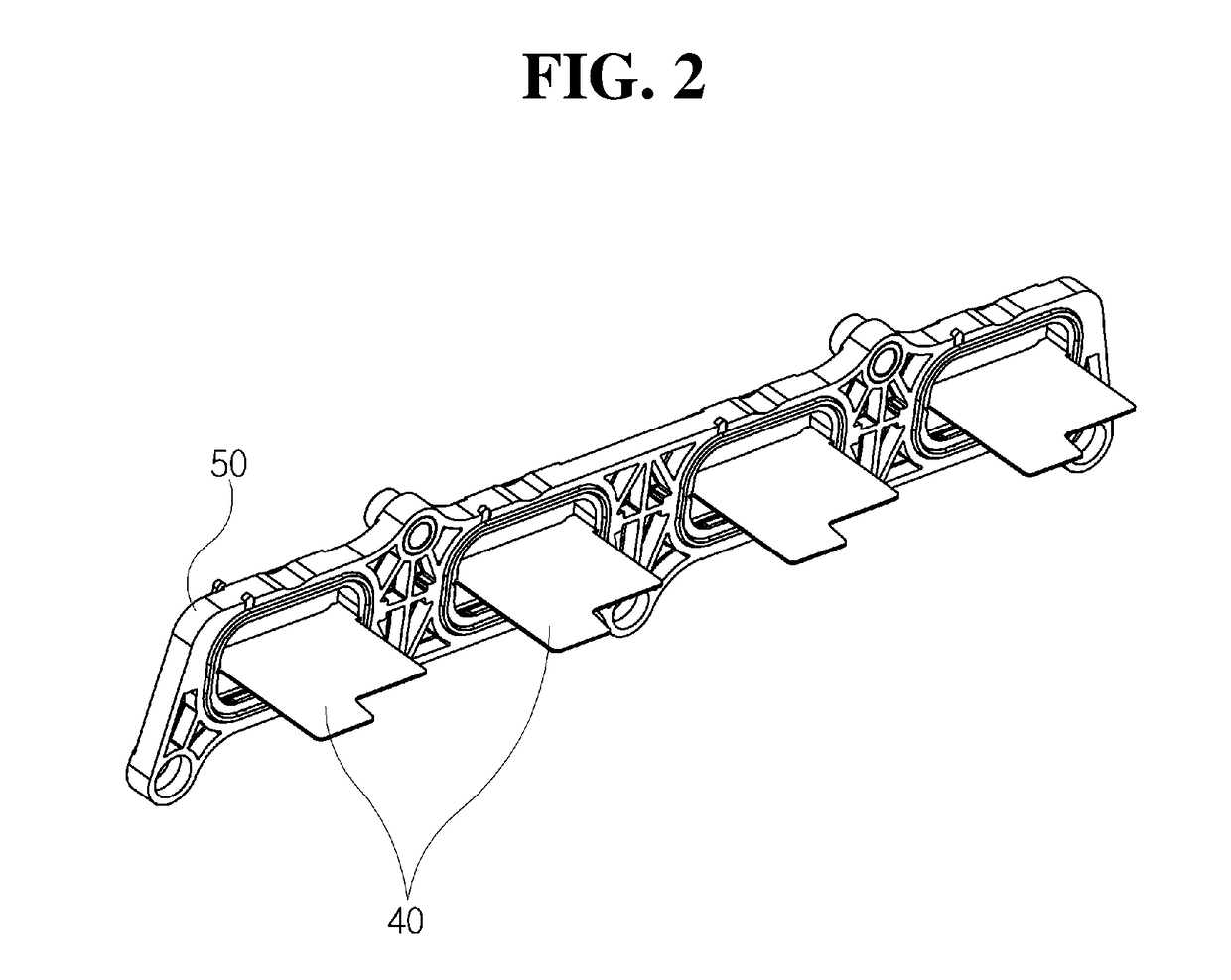
An intake apparatus for an engine is provided. The intake apparatus includes an intake manifold configured to draw intake air thereinto, a cylinder head having an intake port through which intake air drawn from the intake manifold is supplied into a cylinder of the engine and a flow control valve disposed in the intake manifold and configured to control a flow direction of intake air to be drawn from the intake manifold into the cylinder head to generate a circular flow in the intake air. A port plate is configured to reinforce the circular flow of intake air that is generated in the flow control valve and a plate support is coupled with the port plate and coupled between the intake manifold and the cylinder head to enable the port plate to be inserted into the intake port.

Description

CROSS-REFERENCE TO RELATED APPLICATION[0001]This application claims priority to Korean Patent Application No. 10-2016-0156621, filed on Nov. 23, 2016, the disclosure of which is incorporated herein by reference in its entirety.BACKGROUNDField of the Disclosure[0002]Exemplary embodiments of the present invention relate to an intake apparatus for an engine, and more particularly, to an intake apparatus for an engine that supplies intake air drawn from an intake manifold into a cylinder of the engine.Description of the Related Art[0003]Generally, an improvement in performance of an engine includes an increase in a rate that heat generated by combustion is converted into force that displaces a piston of the engine. For example, the combustion speed of fuel should be sufficiently high. An important condition to increase the combustion speed is that air and fuel must be sufficiently mixed within a short time duration due to characteristics of a gasoline engine. A technique for forming ver...

Claims


Application Information

Patent Timeline
Patent Type & Authority Applications(United States)
IPC IPC(8): F02B31/06F02F1/42F02M35/10
CPCF02B31/06F02F1/425F02M35/10262F02M35/10078F02M35/104B29C45/14311B29C2045/14327B29K2705/12B29L2031/7492F02B31/00F02B31/04F02M35/10242F02M35/10255Y02T10/12F02B27/0268F16K1/18
Inventor SEO, CHANG WOOKIM, SUK YOUNGKIM, YOUNG JINKIM, JI SUNHAN, BA RO
Owner HYUNDAI KEFICO CORP
Learn More