Pump jack scaffold system

a scaffold system and push-jack technology, applied in the direction of rod connections, fastening means, constructions, etc., can solve the problems of wasting significant time, affecting the safety of users, and requiring considerable time for safety measures of conventional scaffold systems to connect to the scaffold system

Inactive Publication Date: 2018-05-24
DUPREE CONSTR
View PDF2 Cites 2 Cited by
  • Summary
  • Abstract
  • Description
  • Claims
  • Application Information

AI Technical Summary

Benefits of technology

[0006]The present invention broadly comprises a quick and easy to assemble scaffold. In an embodiment, the scaffold includes end caps that connect to the platform with a removable rod and pin mechanism to resist or prevent users from falling off the end of the scaffold. The scaffold can further include a pole and a mid-rail connector located between a top barrier and a lower platform to prevent the user from falling off a front or back of the scaffold. The pole can be assembled to the scaffold by inserting the pole through connectors and the mid-rail bracket. The scaffold can, therefore, implement safety measures while still being quickly assembled, reducing wasted time and improving the efficiency of the project in which the scaffold is used.
[0008]In another embodiment, the present invention can further include a scaffold including a beam, a rack movably disposed on the beam, a barrier coupled to the rack, a platform coupled to the rack below the barrier, and a mid-rail connector coupled to the barrier between the platform and the barrier. A pole extends through the mid-rail connector to resist or prevent users from falling off the scaffold.

Problems solved by technology

Safety measures are necessary for scaffold systems because users can be seriously injured if they fall off the scaffold platforms.
The safety measures of conventional scaffold systems require considerable time to connect to the scaffold system.
Workers are left waiting for the safety measures to be assembled, wasting significant time and increasing the expense of the project in which the scaffold is used.
Sometimes, to avoid the hassle and expenditure of time, workers forgo assembly and use of the safety measures, thus subjecting themselves to risks of injury or death.

Method used


Image

  • Pump jack scaffold system
  • Pump jack scaffold system
  • Pump jack scaffold system

Examples


Embodiment Construction

[0017]While this invention is susceptible of embodiments in many different forms, there is shown in the drawings, and will herein be described in detail, embodiments of the invention, including a preferred embodiment, with the understanding that the present disclosure is to be considered as an exemplification of the principles of the invention and is not intended to limit the broad aspect of the invention to embodiments illustrated. As used herein, the term “present invention” is not intended to limit the scope of the claimed invention and is instead a term used to discuss exemplary embodiments of the invention for explanatory purposes only.

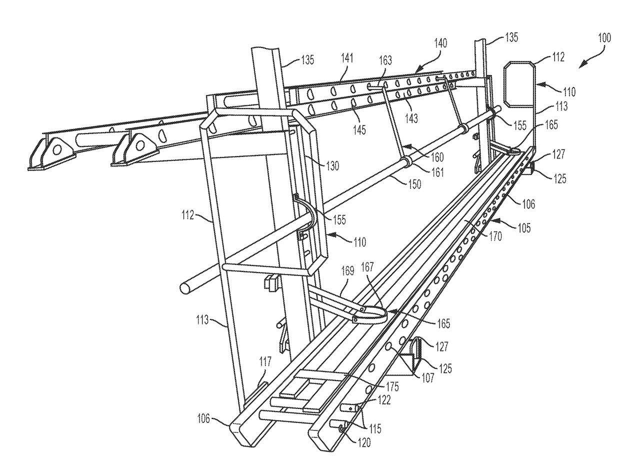
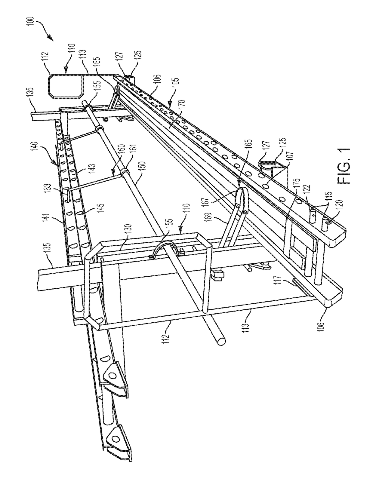
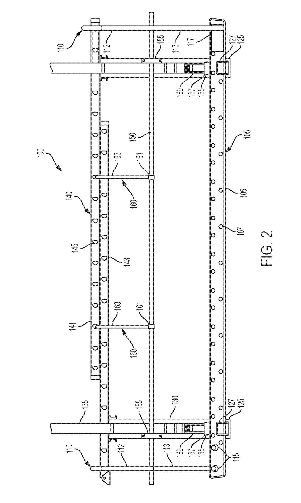
[0018]The present invention broadly comprises a scaffold system with a safety measure that is quick and easy to assemble. For example, the scaffold can include end caps that connect to ends of the platform to resist or prevent users from falling off the end of the scaffold. The end caps are quickly assembled to the scaffold by implementing a remo...


PUM


Abstract

A scaffold that is quick and easy to assemble while still implementing safety measures. The scaffold can include end caps that resist or prevent users from falling off the ends of the scaffold. The end caps are quickly assembled to the scaffold with a removable rod and pin mechanism. Moreover, to prevent a user from falling off the front or back of the scaffold, a pole and a mid-rail connector can be connected to the scaffold across the front or back, respectively, between an upper barrier and a lower platform. The pole can be inserted through connectors that are coupled to the scaffold, and can also be connected to mid-rail brackets for additional structural stability.

Description

CROSS REFERENCES TO RELATED APPLICATIONS[0001]This application is a continuation-in-part application of and claims the benefit of U.S. patent application Ser. No. 14 / 807,374 filed on Jul. 23, 2015, entitled Pump Jack Scaffold System, the contents of which are incorporated herein by reference in their entirety.TECHNICAL FIELD OF THE INVENTION[0002]The present invention relates generally to scaffold systems. More particularly, the present invention relates to a pump jack scaffold system having components that assemble quickly and easily.BACKGROUND OF THE INVENTION[0003]Scaffolds are used in many applications where workers need access to an elevated space. A conventional scaffold includes a movable platform that workers can stand on and that is raised, lowered, or moved side-to-side, depending on the application. Scaffolds are advantageous because they are typically portable and can be reused in various different applications to help workers gain access to elevated spaces.[0004]Pump ja...

Claims


Application Information

Patent Timeline
Patent Type & Authority Applications(United States)
IPC IPC(8): F16B7/04E04G5/14E04G5/00E04G7/02E04G5/06
CPCF16B7/042E04G5/144E04G5/001E04G7/02E04G5/061F16B21/12F16B21/18E04G5/067E04G1/15E04G1/20E04G5/14E04G7/26
Inventor DUPREE, DAVID
Owner DUPREE CONSTR
Why Eureka
Try Eureka