Compensating a sensor signal

Active Publication Date: 2018-05-24
SENSIRION AG
View PDF2 Cites 4 Cited by
  • Summary
  • Abstract
  • Description
  • Claims
  • Application Information

AI Technical Summary

Benefits of technology

[0024]For a reproducible result, the cool-down behavior of the device preferably is reproducible, is captured and is modelled. During applying the dynamic compensation on the heat compensated temperature signal, it is preferred that the target temperature remains constant, or quasi-constant e.g. within a tolerance of 10%, for some time after the component or device is powered-on. Accordingly, the signal dynamics of the target temperature is much slower than the signal dynamics of the device's cool-down behavior. The present idea is further based on the insight that a physical cool-down process in the device can be understood to always continue until it comes to a standstill, even after the component / s is / are switched-on again. In that case the cool-down process continues “underneath” the heat-up process and the resulting impact in the sensed temperature signal can be considered as accumulation of heat-up and cool-down behaviors. This allows to accelerate any potentially remaining cool-down process that contributes to a temperature signal after it is heat compensated with the cold start heat-up characteristics. In case of a real cold start and constant or quasi-constant target temperature, no dynamic residuals contribute to the cold start heat compensated temperature signal, thus a dynamic acceleration applied on a constant signal will have no effect. On the other hand, in case a dynamic residual is still found within the temperature signal after cold start compensation, this residual origins from the still ongoing cool-down process in the device, which means that the component was powered-on in a warm start. The cold start heat compensated temperature signal will—without the suggested adjustment in the frequency spectrum—eventually converge to the correct target temperature value, only that it takes long. Thus, by accelerating a cold start heat compensated temperature signal with the device's cool-down dynamics, the output signal, i.e. a dynamics adjusted heat compensated temperature signal, will approach the target temperature much faster.
[0035]In a different embodiment, the sensor is a humidity sensor for sensing the presence and / or concentration of humidity in the air supplied to the humidity sensor. In this case, the counterpart to the heat emitting components may be device components, e.g. plastic components such as parts of a housing or a circuit board, that are capable to temporarily accept humidity and release humidity even if humid air supply from the ambient no longer is present. Such components may still absorb humidity a certain time after a power-off of the device which temporarily reduces the amount of humidity sensed by the humidity sensor in the event of a warm start of the device. Accordingly, a humidity sensing signal compensated for releasing humidity in a cold start event may still show dynamics in the event of a warm start stemming from a previous operation of the device.

Problems solved by technology

However, such one or more heat emitting components may still be thermally coupled to the temperature sensor, and accordingly to the electronic device.

Method used


Image

  • Compensating a sensor signal
  • Compensating a sensor signal
  • Compensating a sensor signal

Examples


Embodiment Construction

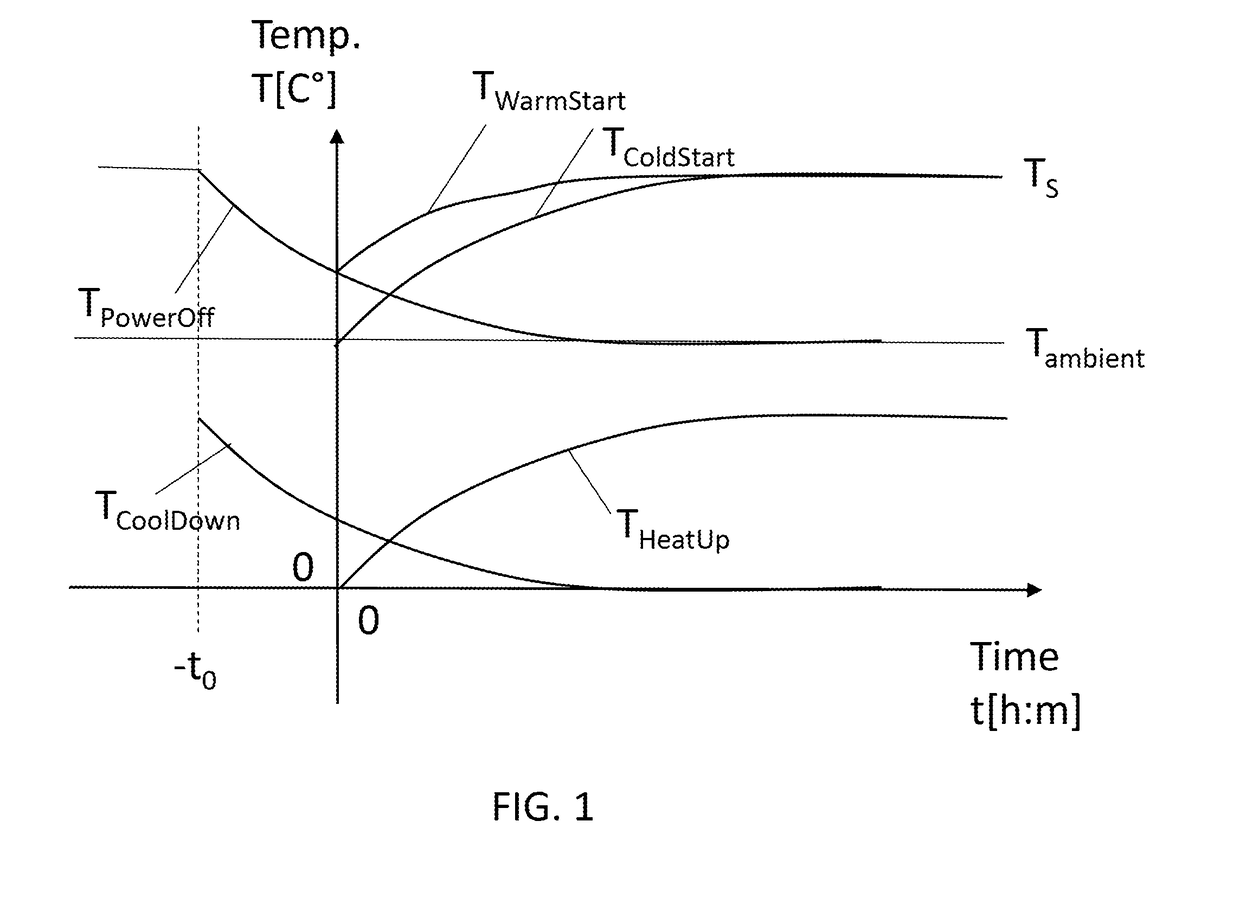
[0043]FIG. 1 shows temperature graphs T in connection with a cold start and a warm start of an electronic device containing heat emitting components inside the device affecting temperature measurement, thereby referring to a method according to an embodiment of the present invention.

[0044]The temperature graphs T are depicted in a temperature T over time t diagram. Temperature T shall be in degrees Celsius, time t in format [hours:minutes].

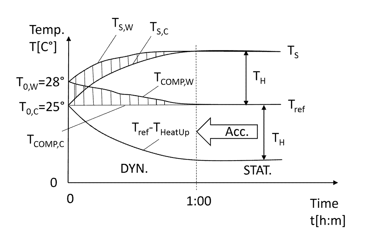
[0045]It is presently assumed that the parameter to be measured by means of a temperature sensor in an electronic device is the ambient temperature Tambient, i.e. the temperature ambient to the electronic device, also referred to as target temperature, or as reference temperature Tref. It is presently assumed that the ambient temperature Tambient is constant in the investigated period in time.

[0046]The graph THeatUp(t) represents a temperature signal that describes a temperature offset in an electronic device due to self-heating after a power-on o...


PUM

PropertyMeasurementUnit
humidityaaaaaaaaaa
timeaaaaaaaaaa
power-on periodaaaaaaaaaa

Abstract

A method for processing a signal supplied by a sensor comprises receiving the sensed signal, and compensating the sensed signal for a contribution caused by one or more components thermally coupled to the sensor. The compensated signal in its dynamics, and the dynamics adjusted compensated sensor signal is provided.

Description

TECHNICAL FIELD[0001]The present invention relates to a method for processing a signal supplied by a sensor, to a sensor signal processing system, and to a related computer program product.BACKGROUND ART[0002]Various components, e.g. electronic components, within electronic devices produce heat during runtime. Although modern electronic devices are increasingly designed to minimize self-heating in order to increase energy efficiency, temperature offsets due to internal heat dissipation remain a common issue that make it challenging to sense e.g. ambient temperature. Prior art estimates ambient temperature or the temperature at a given location by using temperature measurements taken from one or multiple temperature sensors within a device, additional inputs that indicate power consumption and thus heat dissipation of various heat emitting internal components and combining these inputs with appropriate algorithmic methods that compensate the internal heat effects that usually vary ov...

Claims


Application Information

Patent Timeline
Patent Type & Authority Applications(United States)
IPC IPC(8): G01K1/20G01D3/02
CPCG01K1/20G01D3/022G01D3/028G01D3/036G01K7/42
Inventor DIETHER, SALOMONBAUMANN, KRISTIAN
Owner SENSIRION AG
Why Eureka
Try Eureka