
WDM transmission system, central controller for the system, and method for controlling preemphasis in the system

a transmission system and system controller technology, applied in multiplex communication, transmission monitoring, instruments, etc., can solve the problems of high cost of wdm network, inability to adapt to change in one or more variation factors, and inability to adapt to new settings, so as to achieve stablilized transmission of plural wdm signals with ease, and boost costs

Inactive Publication Date: 2006-02-14
FUJITSU LTD
View PDF4 Cites 6 Cited by
  • Summary
  • Abstract
  • Description
  • Claims
  • Application Information

AI Technical Summary

Benefits of technology

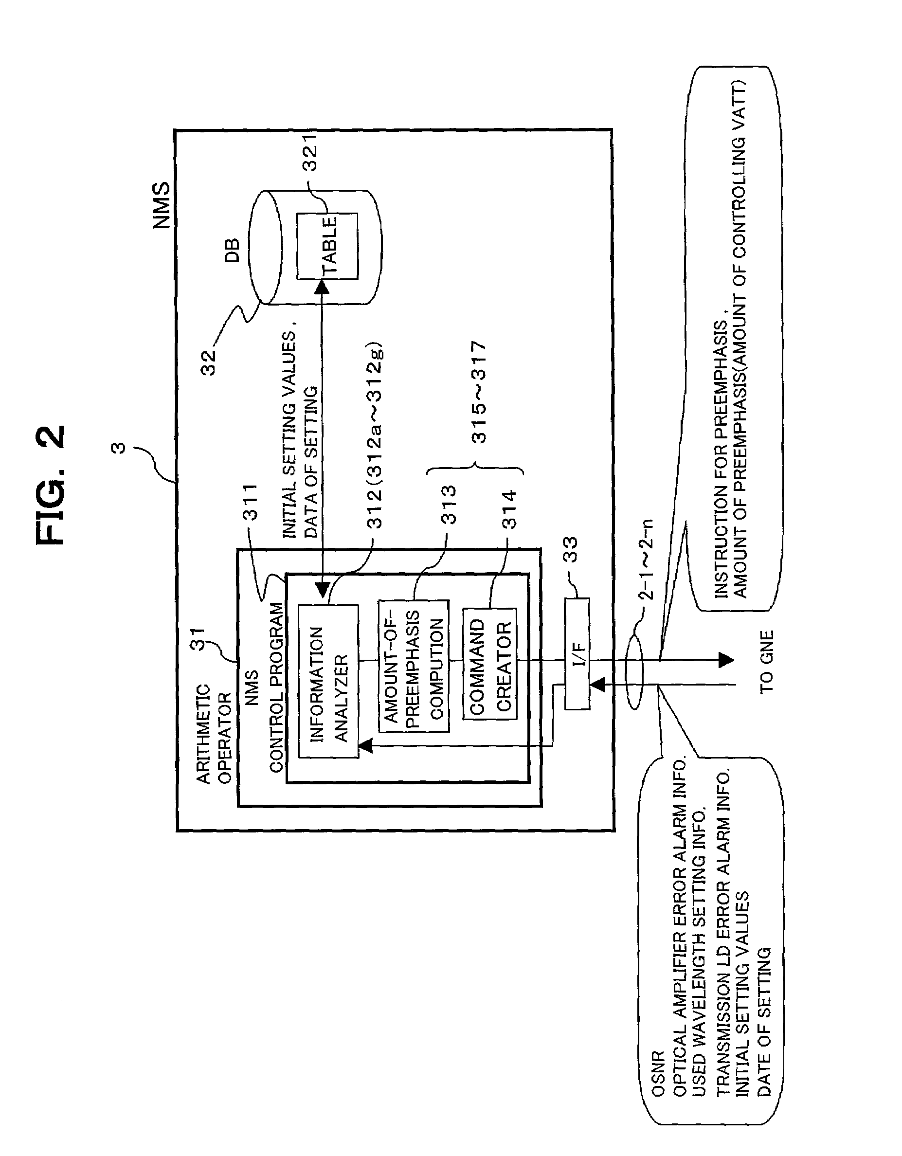
The present invention provides a system for automatically setting preemphasis for optical signals in multiple WDM networks without increasing costs or loads on the apparatuses in the networks. The system includes a central controller that monitors variation factors, such as deterioration of optical transmission lines or light sources, and changes in the number of wavelengths used for optical signals. The central controller communicates with the WDM networks through monitor / control lines and adjusts the settings for preemphasis based on the monitoring results. This automation eliminates the need for manual adjustments and ensures stable transmission of the WDM signals.

Problems solved by technology

However, this conventional preemphasis tends to fail in flexibility to respond to a change in one or more variation factors that causes a new setting for preemphasis (e.g., amounts of preemphasis) due to factors, such as, deterioration of the apparatus over time, change in the number of wavelengths used for optical signals (multiplexed into a WDM signal), or an error arising in a WDM transmission system.
Nevertheless, such a WDM network is expensive and requires a large load to operate.

Method used


Image

  • WDM transmission system, central controller for the system, and method for controlling preemphasis in the system
  • WDM transmission system, central controller for the system, and method for controlling preemphasis in the system
  • WDM transmission system, central controller for the system, and method for controlling preemphasis in the system

Examples


first embodiment

[0028](A)

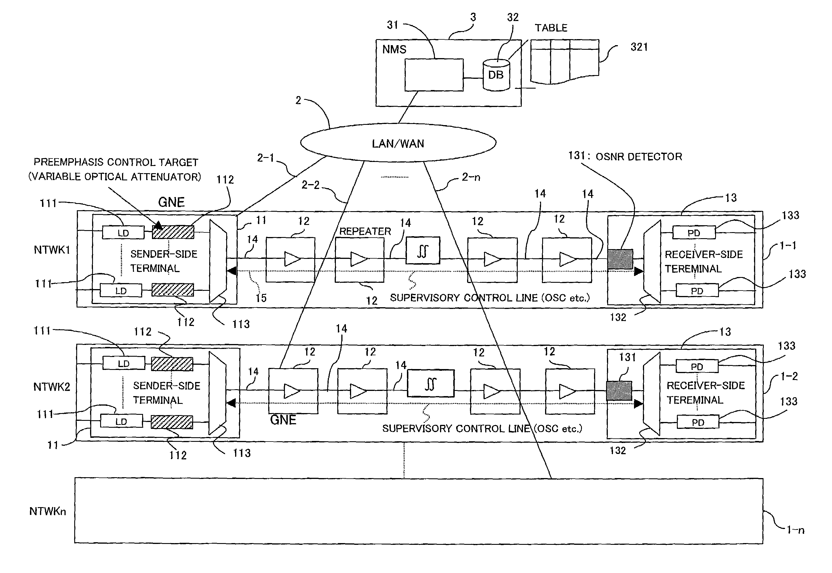
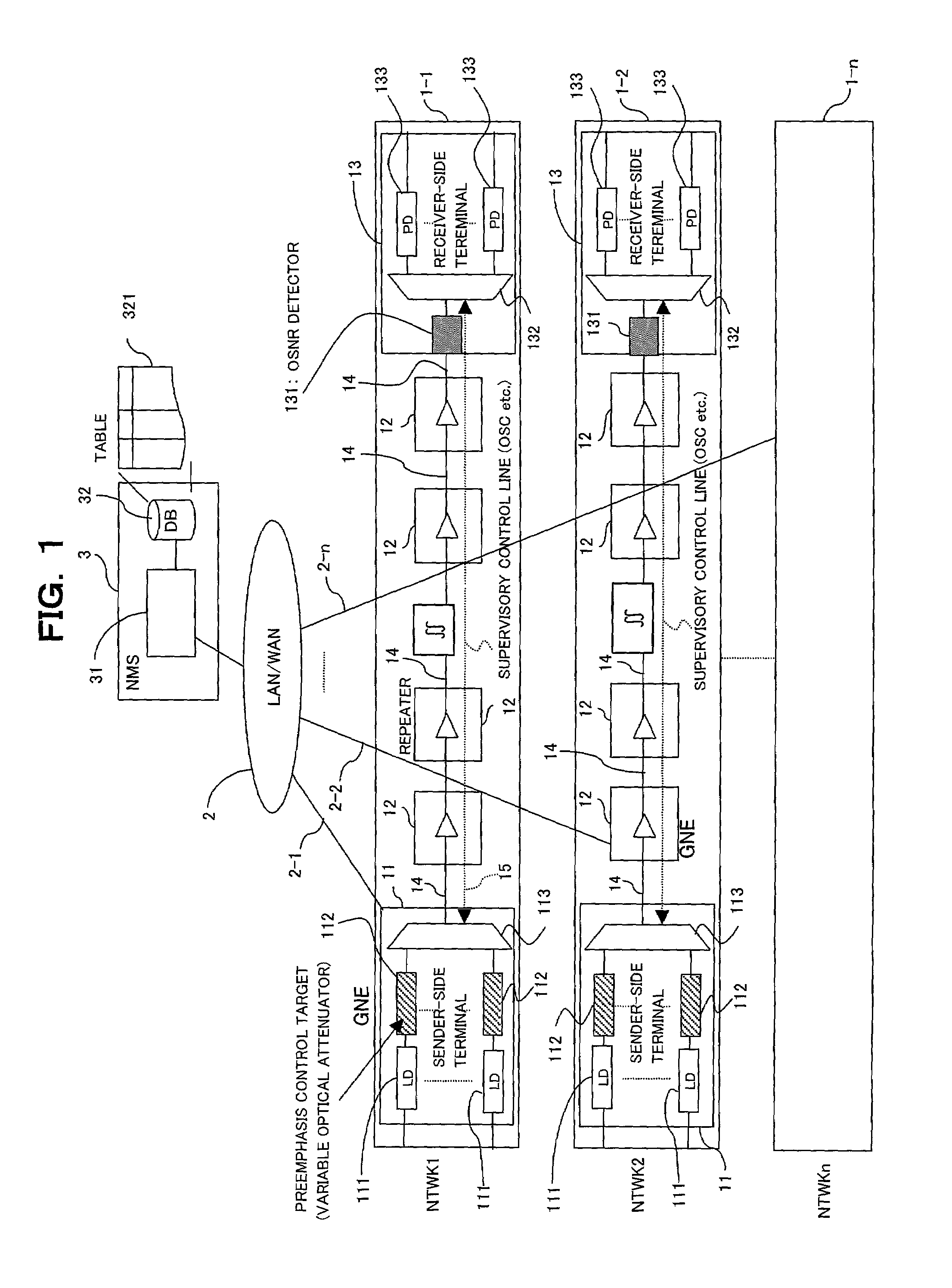
[0029]FIG. 1 shows a WDM (Wavelength Division Multiplexed) transmission system according to a first embodiment of the present invention. The WDM transmission system comprises a plurality of WDM networks 1—1 through 1-n (n is an integer larger than one), and an NMS (Network Management System) server 3, serving as a central controller, which is communicably connected to each WDM network 1-i (where, i is an integer of one through n) via a network 2. Network 2 is exemplified by a LAN (Local Area Network) or a WAN (Wide Area Network) having monitor / control lines 2-1 through 2-n, respectively dedicated to each of WDM networks 1—1 through 1-n. The network 2 performs communication between each of WDM networks 1—1 through 1-n and NMS server 3 via a communication protocol, such as TCP (Transmission Control Protocol) / IP (Internet Protocol) or X.25.

[0030]Each WDM network 1-i comprises WDM terminals 11 and 13 that receive and transmit WDM signals, and one or more WDM apparatuses (repeat...


PUM


Abstract

A WDM transmission system including a plurality of WDM optical network and a central controller communicably connected to the plural WDM optical network via a plurality of monitor / control lines respectively, the central controller includes variation factor monitoring means for monitoring one or more variation factors of preemphasis on each WDM optical network and preemphasis controlling means for controlling a status of the preemphasis by adjusting the setting for the preemphasis performed on each WDM network via respective one of monitor / control lines. Therefore, preemphasis performed each of the plural WDM optical network can be automatically executed without boosting costs and loads on elements of each WDM optical network. Stabilized transmission of a WDM signal can be performed in each of the plural WDM optical network with ease without manual setting.

Description

BACKGROUND OF THE INVENTION[0001]1. Field of the Invention[0002]The present invention relates to a WDM (Wavelength Division Multiplexed) transmission system, a central controller for the system, and a method for controlling preemphasis in the system.[0003]2. Description of the Related Art[0004]Recently, an increased number of WDM transmission apparatuses are being installed within networks for service providers in response to drastic growth in requirements for communication lines, such as the Internet. As a result of the spread of WDM transmission apparatuses, there are demands for proper methods to simplify the optimization and the management of the apparatuses.[0005]In a WDM transmission system, an optical transmitter transmits a WDM signal, into which a plurality of optical signals at respective different wavelengths are multiplexed, is transmitted to an optical receiver via one or more optical repeaters (optical amplifiers), which relay the WDM signal, arranged on the optical tr...

Claims


Application Information

Patent Timeline
Patent Type & Authority Patents(United States)
IPC IPC(8): H04B10/08H04B17/00H04J14/00H04J14/02H04B10/07H04B10/25H04B10/2507
CPCH04B10/0793H04J14/025H04J14/0246H04J14/0227H04J14/0221H04J14/0279H04J14/02216
Inventor YAMAKAWA, SHINYA
Owner FUJITSU LTD
Learn More