A fluid-metering device

a fluid-metering device and fluid-meter technology, applied in the direction of liquid/fluent solid measurement, volume measurement, valve type, etc., can solve the problems of not taking the currency cost of operation, and the known device does not take into account the actual flow of water through the pipe, so as to reduce the flow rate of fluid through the device, the effect of prolonging the usage and prolonging the us

Active Publication Date: 2018-05-31
FLOSTEM LTD
View PDF3 Cites 1 Cited by
  • Summary
  • Abstract
  • Description
  • Claims
  • Application Information

AI Technical Summary

Benefits of technology

[0017]According to a further embodiment of the present invention, there is also provided a fluid-metering device for a hose or pipe, comprising: a body having an inlet and an outlet; flow restriction apparatus for selectively allowing or restricting the flow of fluid through the body, biased from an open position wherein a fluid can flow through the device towards a closed position wherein a fluid cannot flow through the device; latching means comprising: a rotatable member comprising flanges for engaging with the flow restricting apparatus to hold the flow restricting apparatus in the open position, driven by a flow of fluid through the device to disengage with the flow restriction device. The engagement or not of the latching means is more linearly related to the volume flow of water through the device than in prior art systems. As such when there is no fluid flow; the device will not continue to count this time as usage. Indeed, longer usage can be achieved by reducing the flow rate of fluid through the device. This allows the cost of the fluid being used to be more directly linked to operation of the device.
[0018]According to a third embodiment of the invention, there is provided a fluid-metering device for a hose or pipe, comprising: a body having an inlet and an outlet; an impeller drivable by a flow of fluid through the device; flow...

Problems solved by technology

These known devices take no account of the actual flow of water through the pipe.
The conventional timing devices do not take into account the intensity of the flow through the device, or allow for ces...

Method used


Image

  • A fluid-metering device
  • A fluid-metering device
  • A fluid-metering device

Examples


Embodiment Construction

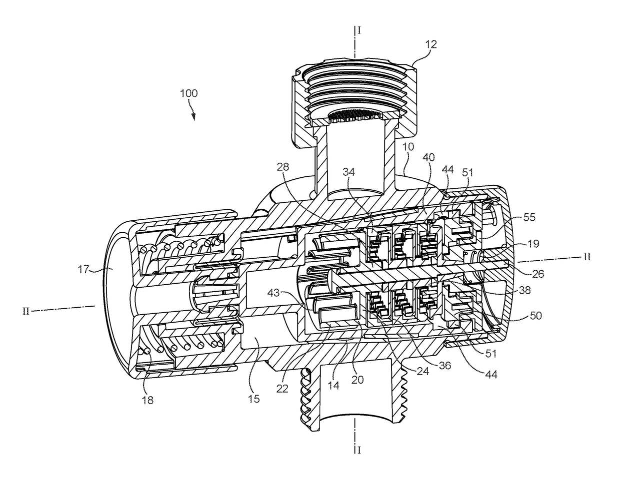
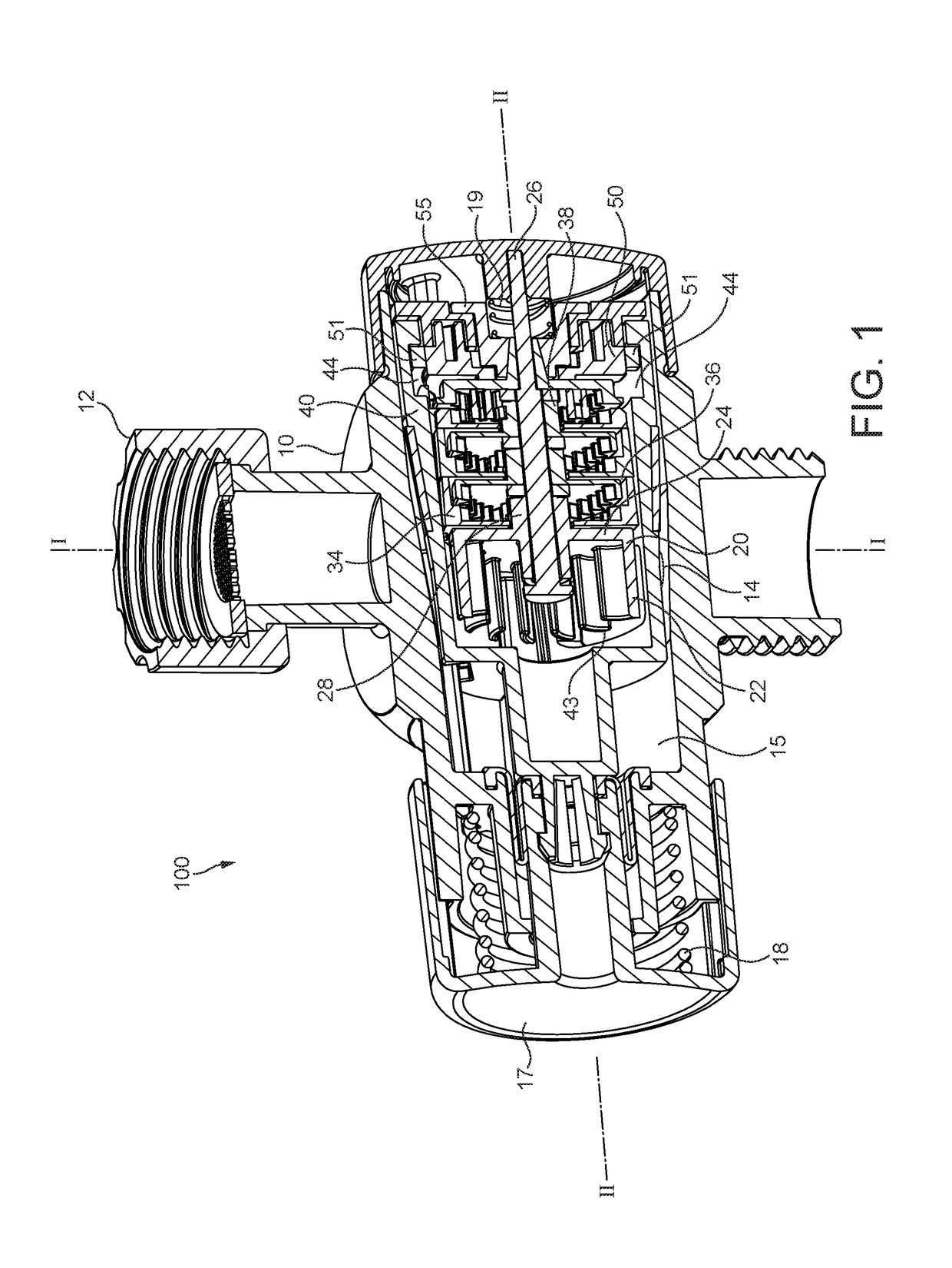
[0026]With reference to FIG. 1, there is shown a fluid-metering device 100 for a hose or pipe. The device comprises a body portion 10 with interchangeable inlet and outlet ports 12, 11. The device 100 could, in alternative embodiments, be formed integrally with pipes extending outwardly in place of ports 11, 12. Each of the inlet and outlet ports is in fluid communication with an inner chamber 15 via subsidiary ports 13, 14. Housed in the inner chamber 15 is a barrel 40, which is slidable in the inner chamber 15 along an axis II between an open position (shown in FIGS. 1 and 4B), and a closed position (shown in FIG. 4A). Attached to the barrel 40 is a depressible member 17, such as a button, which is biased by first biasing member 18. The first biasing member 18 biases the barrel 40 towards the closed position FIG. 4A. The barrel 40 is provided with two cut-out segments 42, 43 which align with the subsidiary ports 13, 14 in the open position of FIG. 1 to allow a fluid to flow throug...


PUM


Abstract

The present invention relates to a device for metering the flow of a fluid. A fluid-metering device for a hose or pipe, comprises: a body (10) having an inlet (12) and an outlet (11); an impeller (20) drivable by a flow of fluid through the device; a barrel (40), having an inlet (42) and an outlet (43), slidably mounted in the body (10) such that the barrel (40) is slidable between an open position wherein the barrel inlet (42) and outlet (43) are aligned with the body inlet (12) and outlet (11) such that a fluid can flow through the device and drive the impeller (20), and a closed position wherein the barrel inlet (42) and outlet (43) are offset from the body inlet (12) and outlet (11) such that a fluid cannot flow through the device, the barrel (40) being biased towards the closed position; and latching means (50) arranged to hold the barrel (40) in the open position, wherein a predetermined number of rotations of the impeller (20) will release the barrel (40).

Description

BACKGROUND OF THE INVENTION[0001]The present invention relates to a device for metering the flow of a fluid.[0002]Devices for supplying a certain amount of water are known. These systems typically achieve fluid-metering by comprising a stop valve connected to a device for measuring a finite period of time and ceasing the flow of fluid after this period of time. These devices are often based upon clockwork or electronic solutions, and are commonly used to meter the flow of water in situations such as garden watering or metered showering.[0003]These known devices take no account of the actual flow of water through the pipe. The conventional timing devices do not take into account the intensity of the flow through the device, or allow for cessation of flow to not be counted. In times of increasing social responsibility, where the environmental as well as monetary cost of the use of natural resources is coming under ever increasing scrutiny it is advantageous to produce a fluid-metering...

Claims


Application Information

Patent Timeline
IPC IPC(8): G01F1/06G01F15/00
CPCG01F1/06G01F15/001G01F15/005A01G25/16A01G25/165F16K21/16G01F11/00E03C2001/026
Inventor MILLER, AUSTEN
Owner FLOSTEM LTD
Why Eureka
Try Eureka