Manufacturing method for rotor core and manufacturing method for motor core
- Summary
- Abstract
- Description
- Claims
- Application Information
AI Technical Summary
Benefits of technology
Problems solved by technology
Method used
Image
Examples
embodiment 1
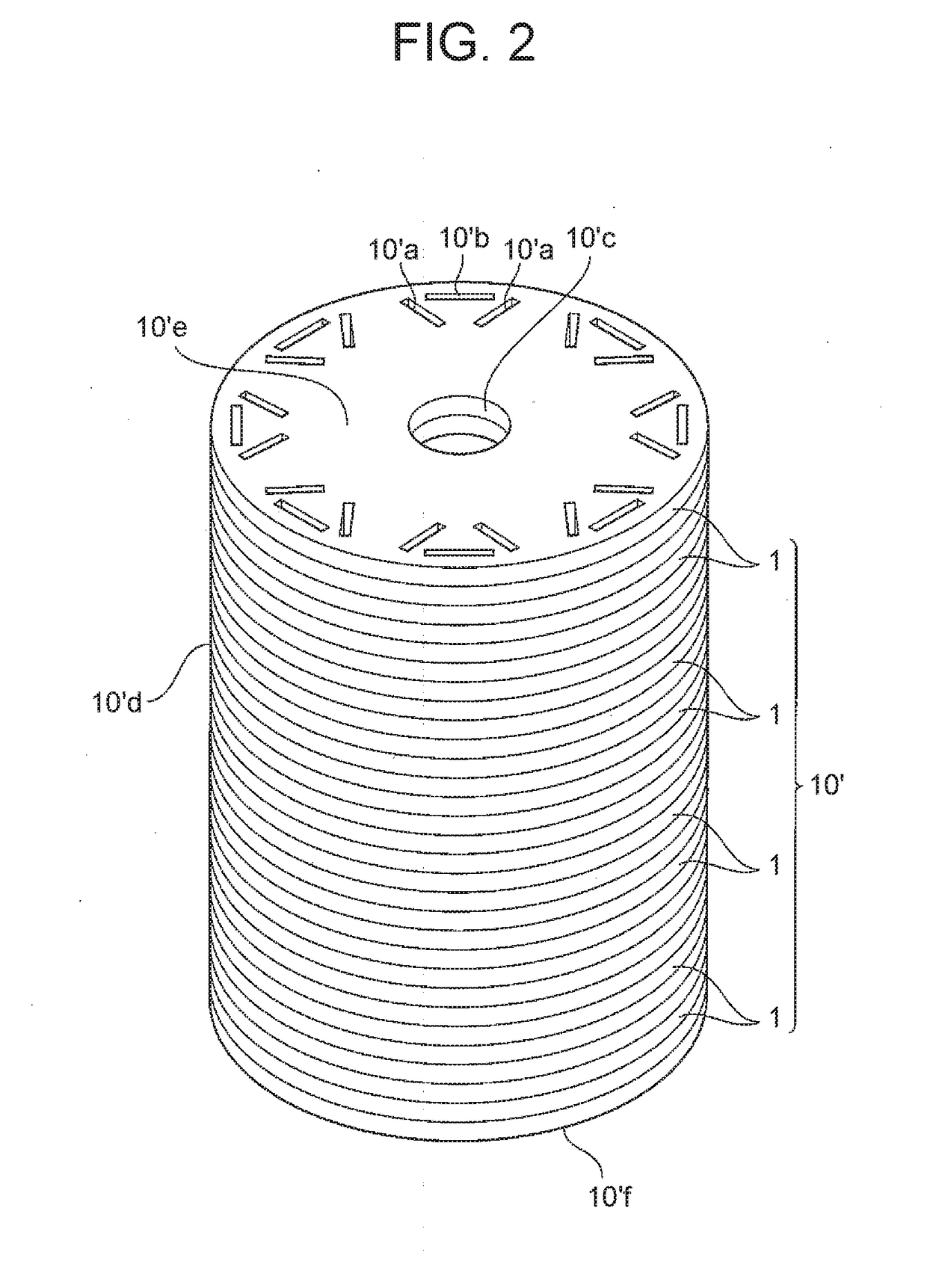
[0058]First, the embodiment 1 of the second step will be described with reference to FIG. 3 and FIG. 4. As shown in FIG. 3, insulating members I are respectively placed on the top surface 10′e and the bottom surface 10′f of the rotor-core precursor 10′, while the side surface 10′d extending in the circumferential direction of the rotor-core precursor 10′ is exposed to the outside, and the rotor-core precursor 10′ in this state is placed in an annealing furnace K1 in which heating units H are incorporated.
[0059]The heating units H are operated so as to heat the rotor-core precursor 10′ from the side surface 10′d thereof (in directions X) in the annealing furnace K1.
[0060]Specifically, in the annealing furnace K1, heat input from the top surface 10′e and the bottom surface 10′f of the rotor-core precursor 10′ is suppressed by the insulating members I, while heat input from the side surface 10′d thereof exposed to the outside is actively carried out. Hence, in the rotor-core precursor ...
embodiment 2
[0065]Next, the embodiment 2 of the second step will be described with reference to FIG. 5. In this embodiment, as shown in FIG. 5, there is used an internally-movable annealing furnace K2 provided with a space for movement MS where the rotor-core precursor 10′ rollingly moves, and also provided with heating units H on the right and the left of the space for movement MS.
[0066]In the internally-movable annealing furnace K2, a pre-heating zone YZ, a high-temperature heating zone HZ, a cooling zone CZ are continuously arranged; and a long gear G2 slidable in the space for movement MS is also provided. The insulating members I are fixed to the top and the bottom surfaces of the rotor-core precursor 10′, an annular gear G1 is fixed to one of the insulating members I, and the gear G1 and the gear G2 are brought to mesh with each other. The long gear G2 is brought to slide (in a direction Z) by a not-illustrated driving unit so as to allow the rotor-core precursor 10′ to rollingly (in a di...
PUM
| Property | Measurement | Unit |
|---|---|---|
| Temperature | aaaaa | aaaaa |
Abstract
Description
Claims
Application Information
 - R&D
- Intellectual Property
- Life Sciences
- Materials
- Tech Scout
- Unparalleled Data Quality
- Higher Quality Content
- 60% Fewer Hallucinations
Browse by: Latest US Patents, China's latest patents, Technical Efficacy Thesaurus, Application Domain, Technology Topic, Popular Technical Reports.
© 2025 PatSnap. All rights reserved.Legal|Privacy policy|Modern Slavery Act Transparency Statement|Sitemap|About US| Contact US: help@patsnap.com


