Manufacturing method for rotor core and manufacturing method for motor core

a manufacturing method and technology for rotor cores, applied in the direction of magnetic circuit rotating parts, furnaces, magnetic circuit shapes/forms/construction, etc., can solve the problems of deteriorating strength, tensile strength, motor efficiency and torque performance, etc., and achieve excellent magnetic characteristics and efficient annealing

Active Publication Date: 2020-02-04
TOYOTA JIDOSHA KK
View PDF23 Cites 0 Cited by
  • Summary
  • Abstract
  • Description
  • Claims
  • Application Information

AI Technical Summary

Benefits of technology

[0015]The outer circumferential region may be defined as a range where the iron loss is relatively great, that is, for example, a range approximately 5 mm more inward from the outer circumferential contour in a circular shape of the stator core. Here, the crystal grains in the outer circumferential region are allowed to grow so as to enhance the magnetic characteristics, to thereby effectively reduce the iron loss in the rotor core.
[0035]While the rotor-core precursor is allowed to rollingly move in the space for movement in the internally-movable annealing furnace, the side surface of the rotor-core precursor is continuously and directly heated by the heating units disposed around the space for movement, to thereby efficiently anneal the rotor-core precursor from the side surface (the outer circumferential region) thereof. On the other hand, the stator-core precursor is placed in the different annealing furnace so as to be annealed such that the grain growth of the crystals is promoted through the entire stator-core precursor, to thereby produce a stator core excellent in magnetic characteristics.

Problems solved by technology

For example, after electricity is inputted, a copper loss resulting from a conductor resistance loss is caused in a coil composing a motor, and an iron loss (or a high-frequency iron loss) resulting from an eddy current loss or a hysteresis loss is caused to a rotor and a stator, so that the motor efficiency and the torque performance become deteriorated depending on these losses.
Unfortunately, it is known that there is a contradiction that the magnetic characteristics are enhanced by grain growth of the crystals in both the stator core and the rotor core through annealing, while strengths (tensile strengths) of the cores become deteriorated due to the grain growth of the crystals.
However, a rotor core manufactured by this method cannot be expected to have the above-described enhancement of magnetic characteristics.
Hence, in the rotor-core steel plates, although enhancement of the magnetic characteristics can be expected, it is concerned that deterioration of strength thereof might be caused, as described above.

Method used


Image

  • Manufacturing method for rotor core and manufacturing method for motor core
  • Manufacturing method for rotor core and manufacturing method for motor core
  • Manufacturing method for rotor core and manufacturing method for motor core

Examples


embodiment 1

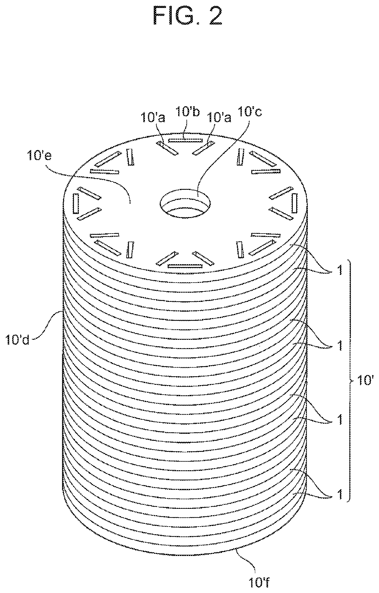
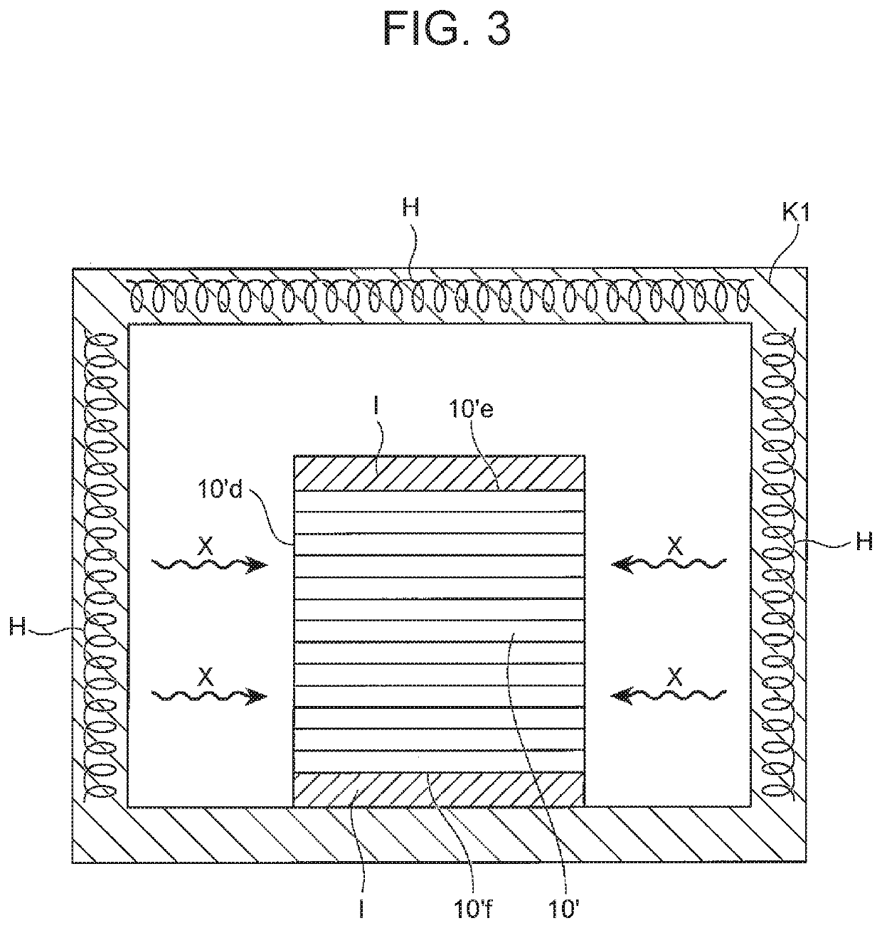
[0058]First, the embodiment 1 of the second step will be described with reference to FIG. 3 and FIG. 4. As shown in FIG. 3, insulating members I are respectively placed on the top surface 10′e and the bottom surface 10′f of the rotor-core precursor 10′, while the side surface 10′d extending in the circumferential direction of the rotor-core precursor 10′ is exposed to the outside, and the rotor-core precursor 10′ in this state is placed in an annealing furnace K1 in which heating units H are incorporated.

[0059]The heating units H are operated so as to heat the rotor-core precursor 10′ from the side surface 10′d thereof (in directions X) in the annealing furnace K1.

[0060]Specifically, in the annealing furnace K1, heat input from the top surface 10′e and the bottom surface 10′f of the rotor-core precursor 10′ is suppressed by the insulating members I, while heat input from the side surface 10′d thereof exposed to the outside is actively carried out. Hence, in the rotor-core precursor ...

embodiment 2

[0065]Next, the embodiment 2 of the second step will be described with reference to FIG. 5. In this embodiment, as shown in FIG. 5, there is used an internally-movable annealing furnace K2 provided with a space for movement MS where the rotor-core precursor 10′ rollingly moves, and also provided with heating units H on the right and the left of the space for movement MS.

[0066]In the internally-movable annealing furnace K2, a pre-heating zone YZ, a high-temperature heating zone HZ, a cooling zone CZ are continuously arranged; and a long gear G2 slidable in the space for movement MS is also provided. The insulating members I are fixed to the top and the bottom surfaces of the rotor-core precursor 10′, an annular gear G1 is fixed to one of the insulating members I, and the gear G1 and the gear G2 are brought to mesh with each other. The long gear G2 is brought to slide (in a direction Z) by a not-illustrated driving unit so as to allow the rotor-core precursor 10′ to rollingly (in a di...


PUM

PropertyMeasurementUnit
crystal grain sizeaaaaaaaaaa
grain sizeaaaaaaaaaa
grain-sizeaaaaaaaaaa

Abstract

A manufacturing method for a rotor core included in a rotor of a motor punches an electromagnetic steel sheet includes punching a plurality of plates for rotor core from an electromagnetic steel sheet; producing a rotor-core precursor by stacking up the plates for rotor core; manufacturing a rotor core by annealing an outer circumferential region of the rotor-core precursor at a first predetermined temperature, and annealing an inner circumferential region of the rotor-core precursor at a second predetermined temperature; the first predetermined temperature being a temperature at which grain growth of crystals of the electromagnetic steel sheet is promoted; and the second predetermined temperature being a temperature at which grain growth of the crystals of the electromagnetic steel sheet is not promoted.

Description

INCORPORATION BY REFERENCE[0001]The disclosure of Japanese Patent Application No. 2016-229199 filed on Nov. 25, 2016 including the specification, drawings and abstract is incorporated herein by reference in its entirety.BACKGROUND1. Technical Field[0002]The present disclosure relates to a manufacturing method for a rotor core included in a motor, and a manufacturing method for a motor core including a rotor core and a stator core that are included in a motor.2. Description of Related Art[0003]In the automobile industry, aiming at further enhancement of driving performance of hybrid vehicles and electric vehicles, developments of higher output performance, weight reduction, and downsizing of drive motors have been promoted day after day. Household electric appliance manufactures have been knuckling down on further downsizing and higher performance of motors incorporated in various household electric appliances.[0004]In order to enhance the motor performance, how much various losses c...

Claims


Application Information

Patent Timeline
Patent Type & Authority Patents(United States)
IPC IPC(8): H02K15/12H02K15/02
CPCH02K15/12H02K15/02H02K15/024Y10T29/49012H02K1/02H02K15/03H02K1/27H02K1/2706Y02T10/64B21D28/06C21D9/0068C21D9/0025C21D8/1272H01F3/02
Inventor TAKAHASHI, TOSHIMITSUTAKEUCHI, SHIGETOTAKAZAWA, MAYUMI
Owner TOYOTA JIDOSHA KK
Why Eureka
Try Eureka