Antenna core and antenna

a technology of antenna core and core, applied in the direction of loop antennas with ferromagnetic cores, magnetic bodies, transportation and packaging, etc., can solve the problems of poor productivity and the soft magnetic characteristics of magnetic powder considered to be deteriorated, and achieve excellent shape machining properties and magnetic characteristics, and short takt time

Inactive Publication Date: 2009-10-29
NAKAGAWA SPECIAL STEEL CO
View PDF15 Cites 2 Cited by
  • Summary
  • Abstract
  • Description
  • Claims
  • Application Information

AI Technical Summary

Benefits of technology

[0013]According to the present invention, provided is an antenna core excellent in shape machining property and magnetic characteristics, and capable of industrially continuous production at a low cost in a short takt time. An antenna formed by winding a conductor around the antenna core of the present invention is excellent in performance and cheap.

Problems solved by technology

However, since an antenna core is produced by a hot press method with the use of a thermoplastic resin as a binder, an antenna core is not taken out from a mold if it is not fully cooled.
Accordingly, when an antenna core is continuously produced, there is a problem such that it takes time for cooling, resulting in a poor productivity.
All of these limitations are to improve soft magnetic characteristics of a magnetic powder or to prevent soft magnetic characteristics from being deteriorated by applying the unnecessarily higher pressure to the magnetic powder.
That is, in the conventional technical knowledge, when a thermosetting resin is used as a binder, soft magnetic characteristics of the magnetic powder are considered to be deteriorated due to shrinkage stress of a resin during a curing process.

Method used


Image

  • Antenna core and antenna

Examples


example 1

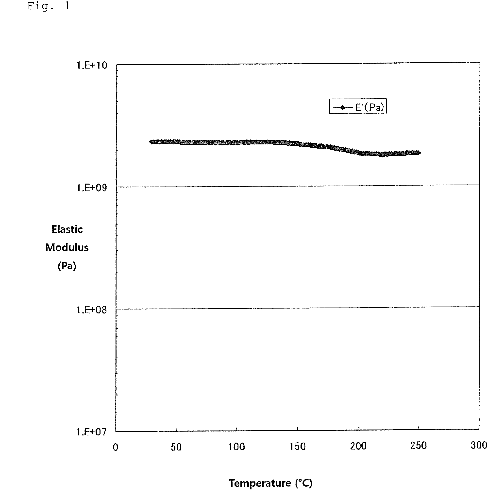
[0062]In order to clarify the inventive step of the present invention relative to the prior art disclosed in Patent Document 1, a soft magnetic metal powder was prepared in accordance with Example 1 of Patent Document 1. Specifically, an alloy having a composition of Fe66Ni4Si14B9Al4Nb3 was made into a molten metal at 1,300 degrees centigrade using a high frequency melting furnace, and the molten metal was allowed to flow downward through a nozzle equipped at the bottom of the melting furnace. The molten metal was finely granulated using a high pressure argon gas of 75 kg / cm2 from a gas atomizing part installed at a tip end of the nozzle. This finely granulated molten metal per se was allowed to collide against a conical rotating cooler having a roll diameter of 190 mm, a vertical angle of 80 degrees and a rotational speed of 7,200 rpm for quickly cooling, whereby a soft magnetic metal powder having a composition of Fe66Ni4Si14B9Al4Nb3 was prepared. This soft magnetic metal powder w...

example 2

[0073]A soft magnetic metal powder was prepared in the same manner as in Example 1, except that a composition of an alloy for preparing a soft magnetic metal powder was changed to CO66Fe4Ni1B14Si15. Specifically, the finely granulated molten metal was allowed to collide against a rotating cooler for quickly cooling, whereby a soft magnetic metal powder in an oval-spherical flat shape was obtained. The soft magnetic metal powder was in a flat shape having an average main diameter of 70 μm, an average minor diameter of 20 μm and an average thickness of 3 μm. The ratio (an average minor diameter / thickness) was 6.7.

[0074]The prepared soft magnetic metal powder was maintained in a stream of nitrogen at a temperature of 380 degrees centigrade for 1 hour, and heat treatment for improving soft magnetic characteristics was carried out. The powder X-ray diffraction of the soft magnetic metal powder after heat treatment was measured. It was confirmed that only a halo pattern specific to the am...

example 3

[0076]An antenna core material was prepared in the same manner as in Example 1 using the same soft magnetic metal powder as that of Example 1, except that product name: EOCN-103 manufactured by Nippon Kayaku Co., Ltd. was used as an epoxy resin and product name: PN-100 (a polycondensate of phenol and formaldehyde) manufactured by Nippon Kayaku Co., Ltd. was used as a curing agent, and the curing agent was used in the amount of 38 weight parts, based on 100 weight parts of the epoxy resin, to give 72 weight % of a ratio of the magnetic metal powder to the binder. An antenna was prepared in the same manner as in Example 1 for evaluating its properties. The results are shown in Table 3.


PUM

PropertyMeasurementUnit
crystallite diameteraaaaaaaaaa
temperatureaaaaaaaaaa

Abstract

An antenna core produced by shaping a soft magnetic metal powder with the use of a resin as a binder, wherein the soft magnetic metal powder is an amorphous soft magnetic metal powder or a nanocrystal-containing amorphous soft magnetic metal powder, of the general formula (1): (Fe1-x-yCoxNiy)100-a-b-cSiaBbMc (1), and wherein the resin as a binder is a thermosetting resin. In the formula, M is at least one element selected from the group consisting of Nb, Mo, Zr, W, Ta, Hf, Ti, V, Cr, Mn, Y, Pd, Ru, Ga, Ge, C, P, Al, Cu, Au, Ag, Sn and Sb. Each of x and y is an atomic ratio and each of a, b and c an atomic %, satisfying the relationships: 0≦x≦1.0, 0≦y≦0.5, 0≦x+y≦1.0, 0≦a≦24, 1≦b≦30, 0≦c≦30 and 2≦a+b≦30.

Description

TECHNICAL FIELD[0001]The present invention relates to an antenna core formed by shaping a specific soft magnetic metal powder with the use of a thermosetting resin and an antenna formed by winding a conductor around this antenna core.BACKGROUND ART[0002]There has been known an antenna core formed by shaping a soft magnetic metal powder with the use of a resin as a binder in view of easy shape machining.[0003]In Patent Document 1, there has been disclosed an antenna core excellent in magnetic characteristics employing a nanocrystal magnetic powder or the like with the use of a thermoplastic resin as a binder. However, since an antenna core is produced by a hot press method with the use of a thermoplastic resin as a binder, an antenna core is not taken out from a mold if it is not fully cooled. Accordingly, when an antenna core is continuously produced, there is a problem such that it takes time for cooling, resulting in a poor productivity.[0004]In Patent Document 1, a resin used as ...

Claims


Application Information

Patent Timeline
Patent Type & Authority Applications(United States)
IPC IPC(8): H01Q7/08H01F1/01
CPCB22F9/082C21D8/12C22C1/0433C22C1/0491C22C33/003C22C33/0257H01F1/15333C22C2200/04C22C2202/02H01F1/15308H01F1/15375H01Q7/06C22C45/02C22C1/047C22C19/07H01Q7/08
Inventor MARUKO, NOBUHIROINADA, KUNIHIROOMI, TAKEHIKOYOSHIDA, MITSUNOBUWATANABE, HIROSHI
Owner NAKAGAWA SPECIAL STEEL CO
Why Eureka
Try Eureka