Adjustable Top Cover Vanes for Controlling Crop Flow in a Rotary Thresher

a rotary thresher and crop flow technology, applied in the field of combines, can solve the problem that the most needed angle adjustment of the top cover vanes is simply not implemented, and achieve the effect of promoting or retarding the flow of material

Active Publication Date: 2018-06-07
TRIBINE IND
View PDF2 Cites 11 Cited by
  • Summary
  • Abstract
  • Description
  • Claims
  • Application Information

AI Technical Summary

Benefits of technology

[0008]Disclosed is a harvesting combine rotor cage top cover assembly that includes an overhead roof formed from a substantially horizontal flat section and downwardly angled side sections. A series of substantially parallel vanes are located beneath the overhead roof. Each vane is formed from a sub

Problems solved by technology

This adjustability is accomplished by means of wrenches and pry bars, at some significant human distress given that there are significant quantities of irritating crop dust present.
This necessarily requires that the vane physically deform within the elastic range of the steel in the vanes, leads to significant re

Method used


Image

  • Adjustable Top Cover Vanes for Controlling Crop Flow in a Rotary Thresher
  • Adjustable Top Cover Vanes for Controlling Crop Flow in a Rotary Thresher
  • Adjustable Top Cover Vanes for Controlling Crop Flow in a Rotary Thresher

Examples


Embodiment Construction

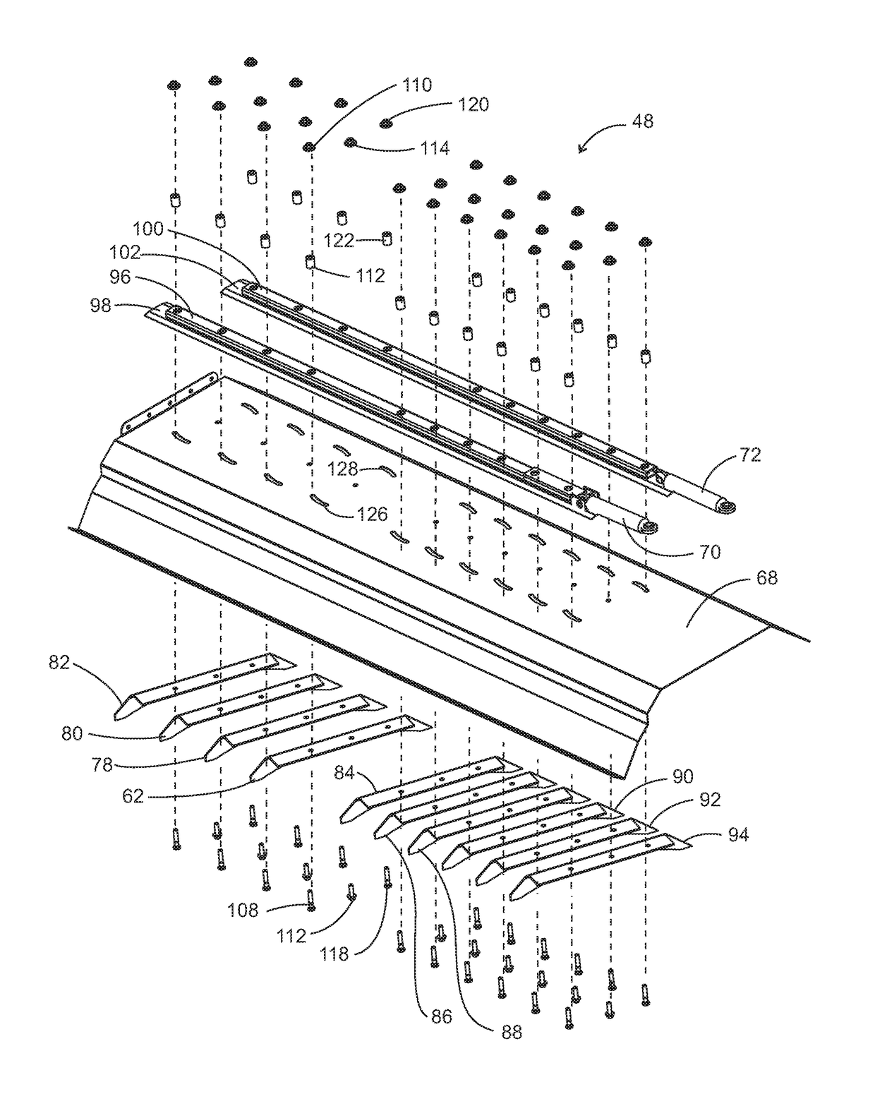
[0025]This disclosure provides a unique and much needed threshing improvement by disclosing a significantly new top cover configuration that allows the vanes to be gang moved by linear actuators, such as, hydraulically powered linear actuators. An enabling design feature that fosters the new top cover of the rotor cage is the new concaves and grates design that effectively wrap around roughly ±270° of the lower cage of considerably larger diameter than current rotary threshers, as disclosed in commonly owned application Ser. No. 14 / 967,691, referenced above. Since the radius of curvature of the (shorter) top cover is so large, the greater part of this cover (middle portion) can be flat, letting the curvature of the bottom (crop engaging) edge of the gang of vanes provide the virtual curvature for the crop to flow. This flat section allows for the positioning of vanes on a surface that allows them to slide fore and aft when forced to do so. The vanes are not required to structurally ...


PUM


Abstract

Disclosed is a harvesting combine rotor cage top cover assembly that includes an overhead roof formed from a substantially horizontal flat section and downwardly angled side sections. A series of substantially parallel vanes are located beneath the overhead roof. Each vane is formed from a substantially flat top section located against the roof horizontal flat section and downwardly laterally extending legs being angled on their sides and having an arcuate bottom. The sides of the vanes are rotatable about a central pivot for promoting or retarding the flow of material in the rotor cage.

Description

CROSS-REFERENCE TO RELATED APPLICATIONS[0001]This application claims benefit of U.S. provisional application Ser. No. 62 / 358,624 filed Jul. 6, 2016.STATEMENT REGARDING FEDERALLY SPONSORED RESEARCH[0002]This application is cross-referenced to application Ser. No. 14 / 946,827 filed Nov. 20, 2015; Ser. No. 14 / 946,842 filed Nov. 20, 2015; and Ser. No. 14 / 967,691, filed on Dec. 14, 2015.BACKGROUND[0003]The present disclosure relates to harvesting combines that use rotary threshing of severed crop and more particularly to controlling the rate of crop flowing through the rotary threshing system and, consequently, threshing aggression, separation efficiency, and power consumption.[0004]In a grain harvesting machine that uses the rotary type of threshing and separating process where the crop enters one end of the rotor encasement (cage) and is turned around and around in that cage by the spinning rotor with threshing element protrusions on its outer skin, it is normal to have long, blade like...

Claims


Application Information

Patent Timeline
IPC IPC(8): A01F7/06
CPCA01F7/067A01D41/127A01D41/12B60K11/08B60K11/04B60Y2200/22B60Y2200/222A01F12/181A01F12/28
Inventor MATOUSEK, ROBERT A.CLAERHOUT, BRYAN S.
Owner TRIBINE IND
Why Eureka
Try Eureka