Conical Collimator for X-ray Measurements

a collimator and x-ray technology, applied in the field of x-ray fluorescence measurement, can solve the problems of increasing the irradiation of the sample, affecting the x-ray intensity, and taking a significant time, and achieve the effect of increasing the x-ray intensity

Active Publication Date: 2018-06-07
PANALYTICAL BV
View PDF9 Cites 3 Cited by
  • Summary
  • Abstract
  • Description
  • Claims
  • Application Information

AI Technical Summary

Benefits of technology

[0015]The inventors have realised that by using an energy dispersive geometry, in combination with a conical collimator, it is possible to greatly increase the solid angle of the source or detector viewed from the central measurement spot and hence increase the intensity of X-rays. In this way, considerably reduced measurement time can be achieved for measuring a small spot.
[0016]Alternatively, the use of a conical collimator may permit a smaller spot to be achieved while still maintaining sufficient X-ray intensity for measurement in a reasonable time scale.
[0021]Where the conical collimator is placed between the sample and the detector, providing a range of output solid angle, there is a need to avoid excessive collimation of the source X-ray beam incident on the sample since the variation of angles of incidence of the beam should at least equal the variation of angles of output across the conical X-ray collimator.
[0022]Similarly, where the conical collimator is placed between the sample and the source, there is again a need to avoid excessive collimation between the sample and the detector.

Problems solved by technology

The problem with this approach is that the intensity of X-rays from the small spot is limited.
Therefore, measurement can take a significant time and result in increased irradiation of the sample.

Method used


Image

  • Conical Collimator for X-ray Measurements
  • Conical Collimator for X-ray Measurements
  • Conical Collimator for X-ray Measurements

Examples


Embodiment Construction

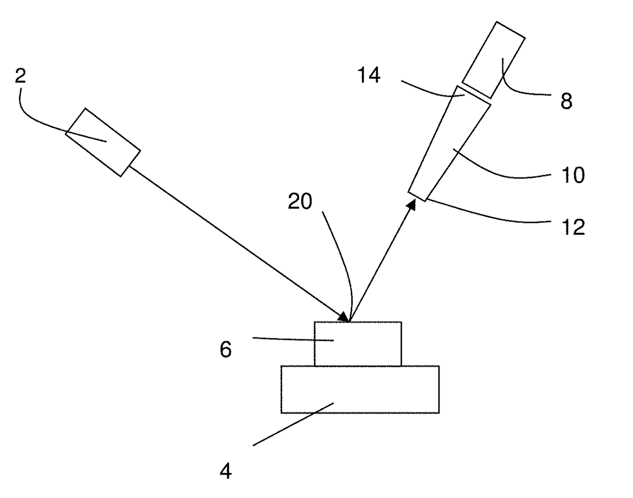
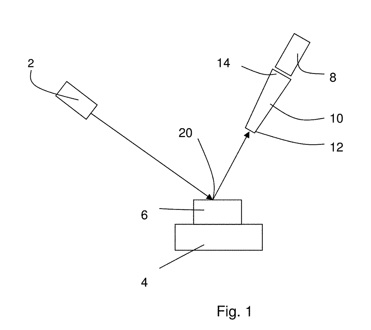
[0039]Referring to FIG. 1, X-ray apparatus includes an X-ray source 2, a sample stage 4 shown with a sample 6 and an energy dispersive X-ray detector 8. Such an arrangement is used in particular for X-ray fluorescence.

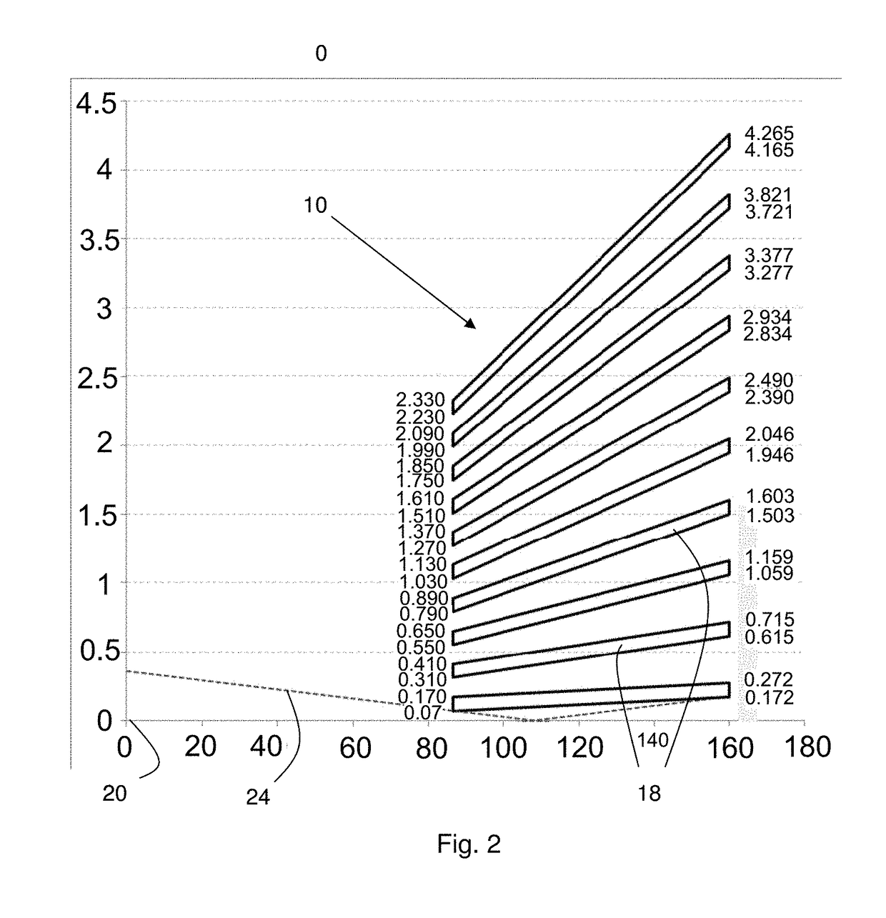
[0040]A collimator 10 is mounted in front of the energy dispersive X-ray detector 8 extending a central end 12 close to the sample stage to an outer end 14 adjacent to the detector as illustrated in more detail in FIG. 2. FIG. 3 shows a perspective view of the collimator 10.

[0041]The collimator 10 is made of a plurality of truncated cones 18 each formed of a metal, in the example the refractive metal tungsten. Note that FIG. 2 shows a section through the collimator and the space between the collimator and the focal spot 20 as well as the vanes 18 in a graphical format in which the vertical axis is highly exaggerated compared with the horizontal axis—the scales on both axes are in mm.

[0042]The sheets are a nominal 0.10 mm thick. Each sheet is formed into a truncated con...


PUM

PropertyMeasurementUnit
thicknessaaaaaaaaaa
diameteraaaaaaaaaa
diameteraaaaaaaaaa

Abstract

X ray apparatus includes a sample stage (4) for supporting a sample (6), an X-ray source (2) and an energy dispersive X-ray detector (8). A conical X-ray collimator (10) is provided either between the sample and the X-ray source or between the sample and the energy-dispersive X-ray detector, the conical X-ray collimator including a plurality of truncated cones arranged concentrically around a central axis, the truncated cones having a common apex defining a central measurement spot on the sample.

Description

FIELD OF INVENTION[0001]The present invention relates to X-ray fluorescence measurements and apparatus for measuring the same.BACKGROUND TO THE INVENTION[0002]A variety of different types of X-ray measurements are possible for analysing materials. In an X-ray fluorescence measurement, a beam of X-rays is directed at a sample and the resulting X-rays emitted by the sample are measured by an energy dispersive X-ray detector. Such a detector measures X-ray intensity as a function of energy or equivalently as a function of wavelength.[0003]For homogenous samples, including large crystalline structures, the sample area measured is often not critical. However, some samples such as powder mixtures and others can be inhomogeneous. Alternatively, X-ray measurements may be carried out to measure the inhomogeneity across a sample. In such cases, there is a need to measure X-ray emissions from a small sample spot.[0004]A known approach to such measurements is to use a double pinhole collimator ...

Claims


Application Information

Patent Timeline
Patent Type & Authority Applications(United States)
IPC IPC(8): G01N23/223G21K1/02
CPCG01N23/223G01N2223/316G01N2223/507G21K1/02G01N23/22B22F10/32B22F10/62B22F10/28B22F10/37G01N2223/076B33Y80/00B33Y10/00G21K1/025Y02P10/25G21K2207/00
Inventor HEGEMAN, PETRONELLA EMERENTIANABRONS, GUSTAAF CHRISTIAN
Owner PANALYTICAL BV
Why Eureka
Try Eureka