Liquid-crystal varifocal lens and focal length control method

a liquid crystal varifocal and control method technology, applied in non-linear optics, mechanical vibration separation, instruments, etc., can solve the problems of difficult technique to make transparent electrodes, difficult to achieve both high transparency and low resistivity, etc., and achieve the effect of thinning the produ

Active Publication Date: 2018-06-07
DOSHISHA CO LTD
View PDF2 Cites 11 Cited by
  • Summary
  • Abstract
  • Description
  • Claims
  • Application Information

AI Technical Summary

Benefits of technology

[0004]The present invention has been achieved under the above circumstances, with a problem thereof being to provide a liquid-crystal varifocal lens and a focal length control method which make it possible to achieve a thinner product and change a focal length without using a transparent electrode.
[0018]The present invention renders it possible to provide a liquid-crystal varifocal lens and a focal length control method which make it possible to achieve a thinner product and change a focal length without using a transparent electrode.

Problems solved by technology

In the case where indium tin oxide (ITO) is used, there are problems, for example, in that indium, which is a rare metal, is contained, it is difficult to achieve both high transparency and low resistivity, and the technique to make a transparent electrode is difficult.

Method used


Image

  • Liquid-crystal varifocal lens and focal length control method
  • Liquid-crystal varifocal lens and focal length control method
  • Liquid-crystal varifocal lens and focal length control method

Examples


first embodiment

Liquid-Crystal Varifocal Lens

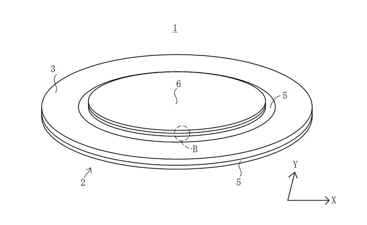
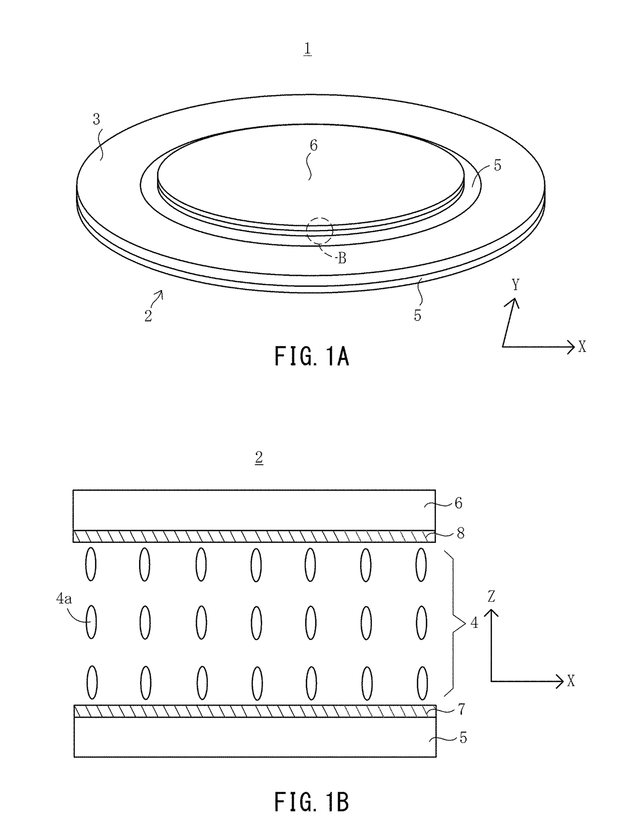
[0035]FIG. 1A illustrates a liquid-crystal varifocal lens 1 according to a first embodiment of the present invention. The liquid-crystal varifocal lens 1 includes a liquid crystal lens 2 formed in a disk shape and an ultrasonic transducer 3 formed in an annular shape.

[0036]As shown in FIG. 1B, the liquid crystal lens 2 includes a liquid crystal layer 4, as well as a first glass substrate 5 (corresponding to the “first substrate” of the present invention) and a second glass substrate 6 (corresponding to the “second substrate” of the present invention), which are disposed opposite each other with the liquid crystal layer 4 positioned therebetween. The first glass substrate 5 and the second glass substrate 6 are respectively provided with alignment films 7 and 8 on respective surfaces on the liquid crystal layer 4 side.

[0037]The first glass substrate 5 is formed in a disk shape with a diameter of 40 millimeters [mm] and a thickness of 0.7 mm. The second gla...

second embodiment

Liquid-Crystal Varifocal Lens

[0068]FIG. 7 illustrates a liquid-crystal varifocal lens 11 according to a second embodiment of the present invention. The liquid-crystal varifocal lens 11 differs from the first embodiment in that a pair of ultrasonic transducers 13A and 13B are included.

[0069]The liquid-crystal varifocal lens 11 includes a liquid crystal lens 12 formed in a disk shape. The liquid crystal lens includes a liquid crystal layer as well as a first glass substrate and a second glass substrate, which are disposed opposite each other with the liquid crystal layer positioned therebetween. The liquid crystal lens 12 is the same as the liquid crystal lens 2 in the first embodiment, except that the first glass substrate and the second glass substrate are in the same size.

[0070]The ultrasonic transducers 13A and 13B are the same as the ultrasonic transducer 3 in the first embodiment, except for position. The ultrasonic transducer 13A is formed in an annular shape and disposed on a ...


PUM

PropertyMeasurementUnit
frequencyaaaaaaaaaa
frequencyaaaaaaaaaa
thicknessaaaaaaaaaa

Abstract

A liquid-crystal varifocal lens includes a liquid crystal lens, and an ultrasonic transducer for generating an ultrasonic wave with a frequency that matches a resonant frequency of the liquid crystal lens. The ultrasonic transducer generates flexural oscillation in the liquid crystal lens such that the flexural oscillation has a vibration intensity decreasing continuously from the center to the circumference of a liquid crystal layer, whereby the thickness of the liquid crystal layer is changed, with the result that the orientation of the liquid crystal molecules is changed.

Description

BACKGROUND OF THE INVENTION1. Field of the Invention[0001]The present invention relates to a liquid-crystal varifocal lens and a focal length control method.2. Description of the Related Art[0002]As one type of optical lens mounted in a camera module, a varifocal lens is known (see, for example, Japanese Laid-Open Patent Publication No. 2001-257932). The focal length of the varifocal lens described in Japanese Laid-Open Patent Publication No. 2001-257932 changes as a result of the lens shape being changed by a piezoelectric actuator. In the case where such a varifocal lens is mounted in a camera module, the thickness of the camera module can be reduced only to a limited degree due to the existence of the piezoelectric actuator.[0003]As another type of optical lens, a liquid-crystal varifocal lens is known (see, for example, Japanese Laid-Open Patent Publication No. 2009-80152). The focal length of the liquid-crystal varifocal lens described in Japanese Laid-Open Patent Publication N...

Claims


Application Information

Patent Timeline
Patent Type & Authority Applications(United States)
IPC IPC(8): G02F1/1335B06B1/06
CPCG02F1/133526B06B1/06G02F2001/294B06B1/0644G02F1/294
Inventor KOYAMA, DAISUKESHIMIZU, YUKI
Owner DOSHISHA CO LTD
Why Eureka
Try Eureka