Laser device

a laser and cavity technology, applied in the direction of laser details, laser output parameters control, semiconductor lasers, etc., can solve the problems of inability to detect the cooling mechanism, the temperature of the laser cavity which is another heat-generating part, and the inability to measure the temperature directly

Active Publication Date: 2018-06-14
FANUC LTD
View PDF3 Cites 3 Cited by
  • Summary
  • Abstract
  • Description
  • Claims
  • Application Information

AI Technical Summary

Benefits of technology

[0008]However, in the technology disclosed in Patent Document 2, there is a problem that, although temperature of a current control element, which is a heat-generating part, is measured by d

Problems solved by technology

However, in the technology disclosed in Patent Document 2, there is a problem that, although temperature of a current control element, which is a heat-generating part, is measured by directly attaching a temperature measuring terminal to the current control element, a temperature of a laser cavity which is another heat-generating part is difficult to be measured directly.
In the technology disclosed in Patent Document 3, th

Method used


Image

  • Laser device
  • Laser device
  • Laser device

Examples


first embodiment

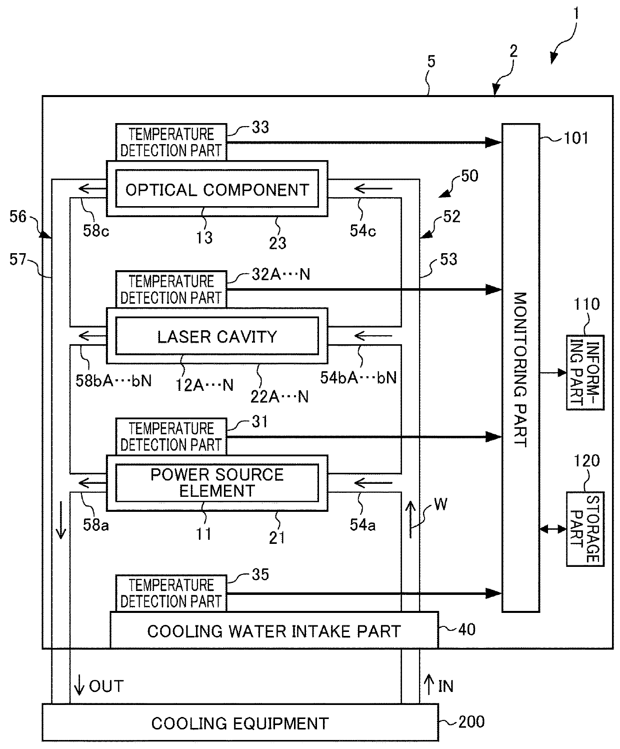
[0024]First, a semiconductor laser device 1 (laser device) is described with reference to FIG. 1. FIG. 1 is a block diagram illustrating a configuration of a laser device according to the first embodiment of the present invention. The semiconductor laser device 1, which is a semiconductor laser device such as of a fiber laser or the like, has a laser oscillator 2 for resonating a laser beam to be output, as shown in FIG. 1. The laser oscillator 2 has a housing 5, with various members and the like housed and disposed inside the housing 5. The laser oscillator 2 is connected to a cooling equipment 200 (cooling device) which is disposed externally, so that cooling water W (refrigerant) can circulate therebetween.

[0025]The laser oscillator 2 has one or a plurality of heat-generating part(s). In the present embodiment, the laser-oscillator 2 includes a power source element 11 (heat-generating part), a plurality of laser cavities 12A to 12N (heat-generating parts), and an optical componen...

second embodiment

[0061]Next, a laser device according to the second embodiment is described with reference to FIG. 3. FIG. 3 is a block diagram illustrating a configuration of a laser device according to the second embodiment of the present invention.

[0062]As shown in FIG. 3, a semiconductor laser device 1A includes a temperature / humidity detection part 38 (internal environment detection part), an adjustment part 141, adjustment parts 142A to 142N, an adjustment part 143, and a control unit 130. The temperature / humidity detection part 38 (internal environment detection part) is configured to be capable of detecting a temperature and humidity of the internal space in the housing 5. The temperature / humidity detection part 38 outputs information on the detected temperature and humidity of the internal space in the housing 5 to the monitoring part 101.

[0063]The adjustment part 141 is disposed on the branch supply passage 54a. The adjustment part 141 is configured to be capable of adjusting the flow amou...


PUM


Abstract

To provide a laser device capable of detecting overheating (abnormality) of a heat-generating part by detecting a temperature of a cooling member for cooling the heat-generating part. A laser device includes one or a plurality of heat-generating part(s), one or a plurality of cooling member(s) respectively disposed in contact with the one or plurality of heat-generating part(s), the one or plurality of cooling member(s) containing a refrigerant flowing inside, one or a plurality of first temperature detection part(s) respectively disposed on the one or plurality of cooling member(s) to respectively detect temperatures of the one or plurality of cooling member(s), and a monitoring part capable of detecting an abnormality respectively in the one or plurality of cooling member(s) based on temperature information including information on the temperatures detected by the one or plurality of first temperature detection part(s).

Description

[0001]This application is based on and claims the benefit of priority from Japanese Patent Application No. 2016-242504, filed on 14 Dec. 2016, the content of which is incorporated herein by reference.BACKGROUND OF THE INVENTIONField of the Invention[0002]The present invention relates to a laser device. More specifically, the present invention relates to a laser device including a cooling member for cooling a heat-generating part.Related Art[0003]A conventional laser device such as a semiconductor laser device has heat-generating parts such as a plurality of laser cavities and an optical component. Each of such heat-generating parts is cooled by a cooling member utilizing cooling water supplied by an external cooling device. The cooling water circulates between the cooling device and the cooling member, so as to be supplied from the cooling device to the cooling member through a supply passage connecting between the cooling device and the cooling member, and to be discharged from the...

Claims


Application Information

Patent Timeline
IPC IPC(8): H01S5/024H01S5/06H01S5/068H01S5/0683
CPCH01S5/02423H01S5/02461H01S5/02453H01S5/0612H01S5/06804H01S5/06837H01S5/02415H01S5/02438H01S5/02446H01S5/0617H01S5/06825H01S5/4025
Inventor NUKUI, TOORU
Owner FANUC LTD
Why Eureka
Try Eureka