Furniture Protector Against Bed Bugs and Other Crawling Insects

a technology for furniture and crawling insects, applied in the field of insect control devices, can solve the problems of bed bugs not being able to climb, debris easily falling in the trap, and clogging the sides of the trap,

Inactive Publication Date: 2018-06-21
UNIV OF FLORIDA RES FOUNDATION INC
View PDF38 Cites 2 Cited by
  • Summary
  • Abstract
  • Description
  • Claims
  • Application Information

AI Technical Summary

Benefits of technology

[0009]A secondary objective of the present invention is to provide traps, coasters, devices, apparatus, systems and methods for preventing and capturing insects that combines a smooth(slick) surface along with or without a sticky surface for protecting furniture from insects, such as bed bugs.
[0013]There are several reasons this invention is superior to vertical smooth sides. The first is that bed bugs have more difficulty crossing the underside smooth(slick) and / or pesticide treated surface upside down. The bugs cannot hang on the surface and fall into the pitfall part of the trap. Therefore, this invention is better for capturing bed bugs. A second reason the trap is superior is that the underside smooth / pesticide surface is protected from debris that falls from the room into the trap. Debris falls on the sides and bottom of the trap, but does not adhere to the inner smooth / pesticide underside surface. Therefore the trap remains effective when used as directed.
[0015]This Invention incorporates one or more of the following elements in order to produce a barrier that prevents bed bugs and other crawling insects from climbing on a piece of furniture.
[0017]The novel pitfall trap barrier can be used to prevent bed bugs and other crawling insects from climbing on a piece of furniture. The inside of the pitfall can optionally be lined with a sticky substance to prevent insect escape. The underside of the barrier is a slick or pesticide treated surface in order to further prevent escape.

Problems solved by technology

These circular traps have pitfall areas with almost vertical sides that are either too smooth for a bed bug to climb or coated with talc so the bugs cannot get a grip to climb.
There are several problems with these types of traps.
Debris easily falls in the traps and coats the sides with dirt.
Bed bugs can, over time, climb these smooth or talc-coated surfaces, so bed bug escape from these traps can occur.
However, traditional sticky traps have problems in trapping bed bugs.
However, test data has shown that using too smooth of a surface causes a behavior problem where the bed bug actually avoids traveling on the smooth.
For example, U.S. Pat. No. 5,572,825 to Gehret describes a glue trap having a slippery surface about the perimeter that does not allow for the cockroach to have enough leverage to remove themselves from the sticky trap.
The problem is that the “silicone coated .
A major problem in motels and hotels is the proliferation of bed bug type insects that can travel from the floor up legs of furniture.
The above devices are not capable of stopping and preventing all bed bugs from climbing from a floor location up legs to furniture, such as beds, and the like.

Method used


Image

  • Furniture Protector Against Bed Bugs and Other Crawling Insects
  • Furniture Protector Against Bed Bugs and Other Crawling Insects
  • Furniture Protector Against Bed Bugs and Other Crawling Insects

Examples


first embodiment

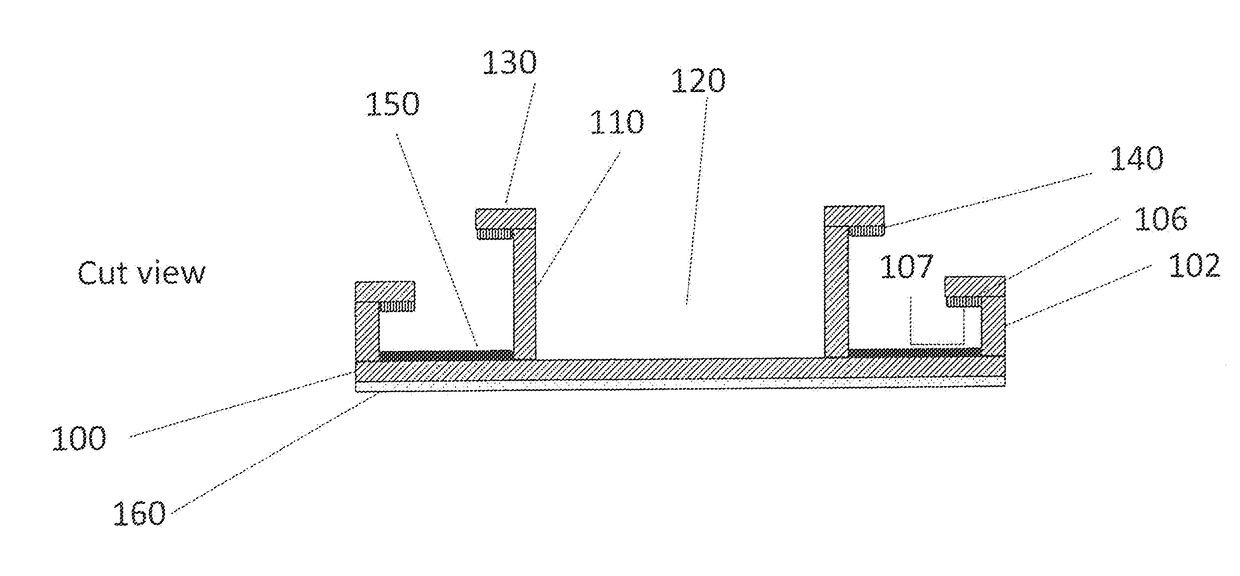
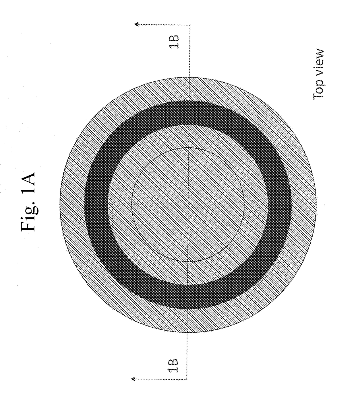
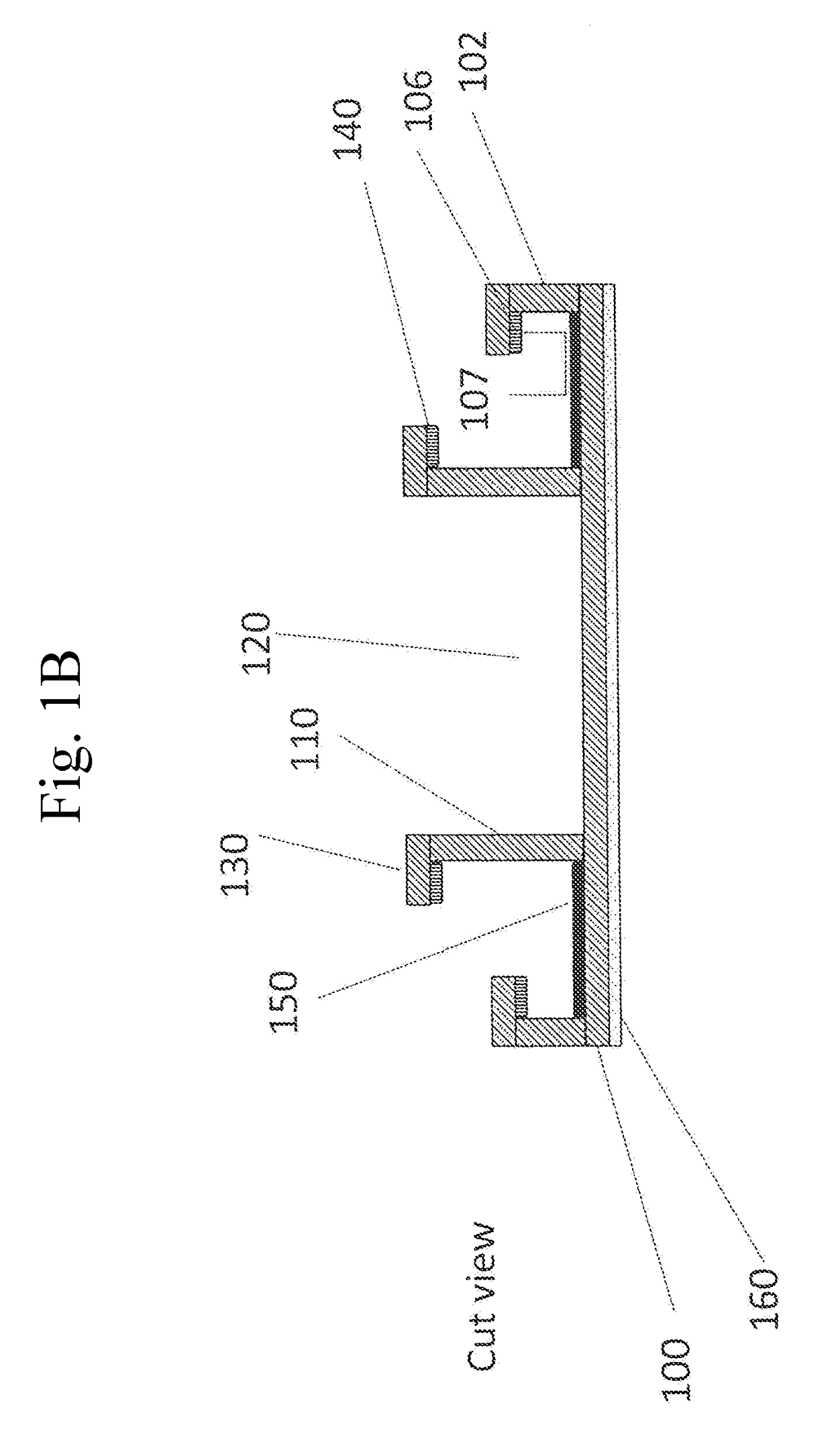
[0073]FIG. 1A is a top view of a trap barrier. FIG. 1B is a cross-sectional view of the trap barrier of FIG. 1A along arrows 1B.

[0074]Referring to FIGS. 1A-1B, the trap barrier can include a solid base bottom 100 having a generally ring shaped pit or moat with a sticky surface 150 and an inner wall 110 for supporting a furniture leg inside of a well area 120 and having an outwardly bent edge 130 with a lower facing surface having a smooth surface or pesticide treated surface.

[0075]The barrier can have an outer wall 102 having an inwardly bent edge 106, with an undersurface 107 that can have a smooth(slick) or pesticide-treated surface. Additionally, the undersurface can be both a smooth(slick) surface with a pesticide treated surface.

[0076]The inner wall 110 can have a greater height than the outer wall 102. Underneath the base bottom 100 can be a surface 160 such as a slick surface to facilitate moving furniture that is supported by the barrier. Here, the outer wall 102 is generall...

second embodiment

[0080]FIG. 2A is a top view of a second embodiment trap barrier. FIG. 2B is a cross-sectional view of the trap barrier of FIG. 2A along arrows 2B.

[0081]The embodiment in FIGS. 2A-2B is similar to that in the previous embodiment, with the exception of having the outer wall 104 angled inwardly from the base portion 100.

third embodiment

[0082]FIG. 3A is a top view of a third embodiment trap barrier. FIG. 3B is a cross-sectional view of the trap barrier of FIG. 3A along arrows 3B. FIG. 3C is a bottom view of the trap barrier of FIG. 3A.

[0083]A base portion 300 can form a protector top having a furniture attachment peg extending upward from a mid portion of the base for insertion into a bottom of a furniture leg. Extending below the base can be a downwardly protruding outer side wall 310 forming a channel therein with a furniture support leg 350 extending downwardly from a mid portion of the base. A channel can include a lower facing surface 340 having one of the smooth surface or the pesticide treated surface. The furniture support leg 350 is large enough to raise the outer side wall 310 above the floor support surface.


PUM


Abstract

Pitfall traps, coasters, devices, apparatus, systems and methods for capturing crawling insects, such as bed bugs, and / or for preventing the insects from climbing up furniture legs to furniture such as beds, cots, chairs and any type of furniture where a person would rest or sleep. Smooth slick surfaces and / or pesticide treated surfaces can be located on underside facing horizontal or angled surfaces used with or without sticky surfaces which all can be used to prevent insect and bed bug travel and assist in helping trap the insects and bed bugs.

Description

CROSS REFERENCE TO RELATED APPLICATION[0001]This application is a Continuation of Patent Cooperation Treaty Application PCT / US16 / 16839 filed Feb. 5, 2016, which claims the benefit of priority to U.S. Provisional Application Ser. No. 62 / 112,926 filed Feb. 6, 2015. The entire disclosure of each of the applications listed in this paragraph are incorporated herein by specific reference thereto.FIELD OF INVENTION[0002]This invention relates to insect control devices, and in particular to pit fall traps, coasters, devices, apparatus, systems and methods having underside facing surfaces with smooth (slick) and / or pesticide treated surfaces for allowing the capturing of crawling insects, such as bed bugs, and for preventing insects and bed bugs from climbing up furniture legs to furniture such as beds.BACKGROUND AND PRIOR ART[0003]Circular pitfall traps are the most common way to protect furniture from bed bugs that crawl from the room onto the bed and to monitor bed bug populations. These ...

Claims


Application Information

Patent Timeline
Patent Type & Authority Applications(United States)
IPC IPC(8): A01M1/10A01M1/02
CPCA01M1/103A01M1/00A01M1/10A01M1/02A01M1/14A01M1/20Y02A50/30
Inventor KOEHLER, PHILIP G.PEREIRA, ROBERTO M.HOTTEL, BENJAMIN A.
Owner UNIV OF FLORIDA RES FOUNDATION INC
Why Eureka
Try Eureka