
Ablation of Myocardial Tissues with Nanosecond Pulsed Electric Fields

a nano-second pulsed electric field and tissue technology, applied in the field of biological tissue ablation, can solve the problems of reducing the quality of life of most patients, forming blood clots, and only satisfying pharmacological treatments, so as to reduce the thermal side effects of rf ablation, reduce the control of the ablated volume, and prolong the ablation time

Active Publication Date: 2018-06-21
OLD DOMINION UNIVERSITY RESEARCH FOUNDATION
View PDF8 Cites 0 Cited by
  • Summary
  • Abstract
  • Description
  • Claims
  • Application Information

AI Technical Summary

Benefits of technology

[0016]In some embodiments, using nsPEF ablation results in more precise control of the ablation volume as compared to the use of RF ablation. In these embodiments, improved control of the ablation volume is achieved because the electrical fields generated during nsPEF ablation drop off much more sharply at the boundaries of the ablation volume when using the disclosed electrode configurations as compared to RF ablation where temperature routinely causes tissue damage beyond the intended ablation volume because heat is diffusing from the site of the RF ablation catheter. Further to these embodiments, the increased control aspects of nsPEF ablation reduce the high recurrence rate experienced when utilizing RF ablation. Additionally, ablation of cardiac tissue using nsPEF ablation can ensure a more uniform lesion thickness thereby reducing the likelihood of the recurrence of Atrial Fibrillation (AF).
[0018]In some embodiments, nsPEF ablation is performed at specific tissue location sites for a duration from about 1 second to about 2 seconds per site treated. This compares to RF ablation techniques that generally require durations from about 15 seconds to about 60 seconds. nsPEF ablation significantly reduces treatment time and is a major improvement for both the individual patient and the ablation treatment centers where increased capacity will lead to rapidly satisfying the demand for ablation procedures.
[0022]In some embodiments, a general advantage of the electrode configurations is the improved control and uniformity of the volume and boundary of ablated tissue.
[0025]The present disclosure leads to enhanced treatments of a plurality of cardiac arrhythmias, especially atrial fibrillation (AF). The significant results from various tests confirm that nsPEF ablation of myocardial tissues is a treatment that addresses all of the drawbacks in current art. In an aspect of the present disclosure, the risk to patients from using nsPEF ablation methods is reduced since many risks depend directly on the length and cost of the procedure.

Problems solved by technology

Most of these patients have seen their quality of life significantly reduced.
Unfortunately, pharmacological therapy only yields satisfactory results in about half of the patients so prescribed [5].
The underlying reason for recurrent AF is because the lesions created during the RF ablation procedure become conductive again due to the limited control over the geometry of the ablated volume (e.g., created lesions do not exhibit a consistent width) during the RF ablation procedure.
Thermal side effects include the formation of blood clots (e.g., thrombus formation), charring, steam pops, and thermal damage to adjacent tissues, such as the esophagus.
While irrigated catheters maintain the catheter tip temperature and the tissue surface temperature at substantially lower temperatures, thermal side effects remain a major concern.
Cryoablation exhibits drawbacks including phrenic nerve palsy, longer ablation times, and lower control of the ablated volume than RF ablation.
Additionally, another limitation of using cryoablation is that the endocardial freezing process needs a bloodless field and the lesion created is not a complete transmural lesion as is created during RF ablation [13].

Method used


Image

  • Ablation of Myocardial Tissues with Nanosecond Pulsed Electric Fields
  • Ablation of Myocardial Tissues with Nanosecond Pulsed Electric Fields
  • Ablation of Myocardial Tissues with Nanosecond Pulsed Electric Fields

Examples


examples

[0103]The following examples and results are presented solely for illustrating the various embodiments in the present disclosure and are not intended to limit the various embodiments in any way.

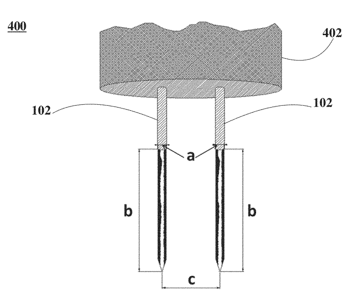
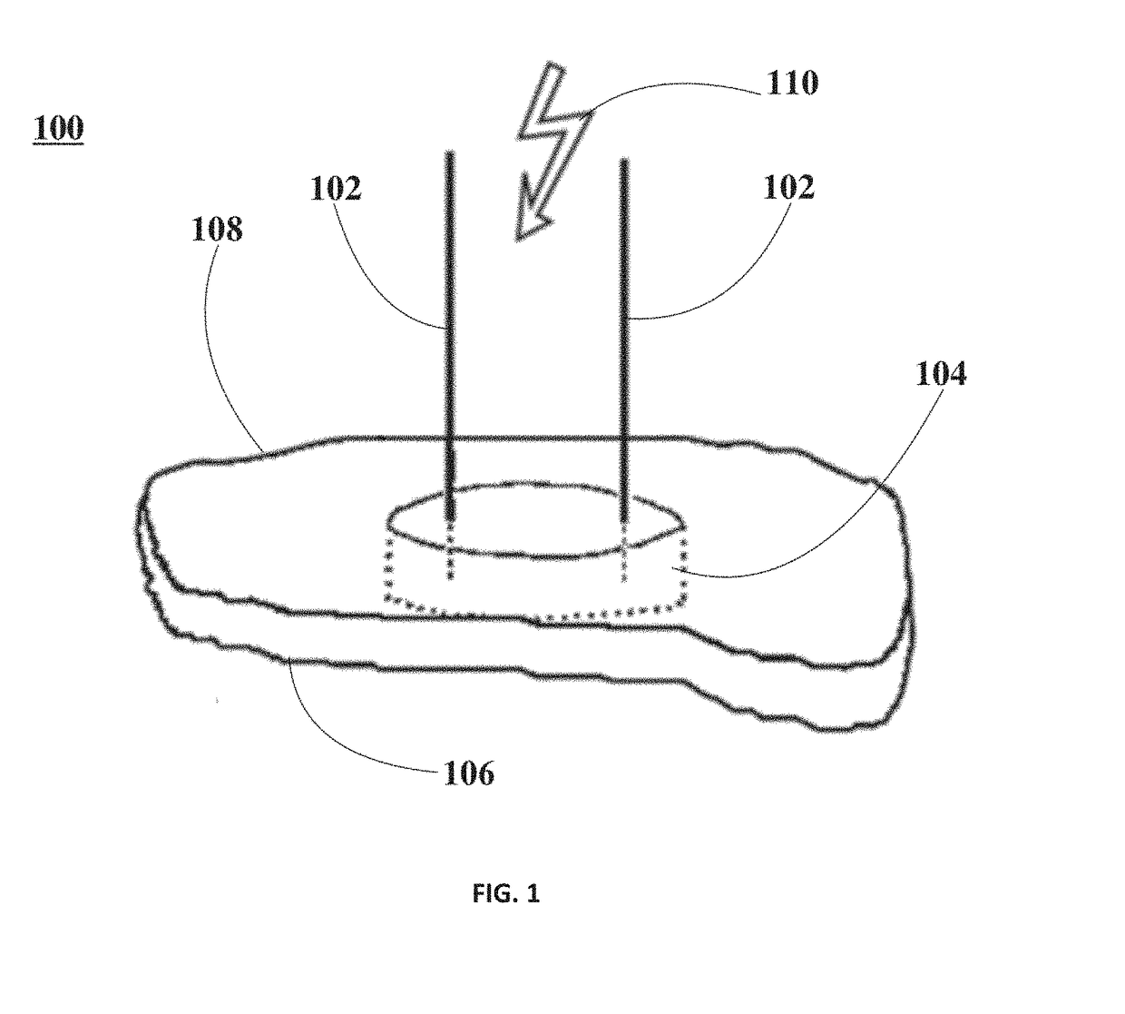
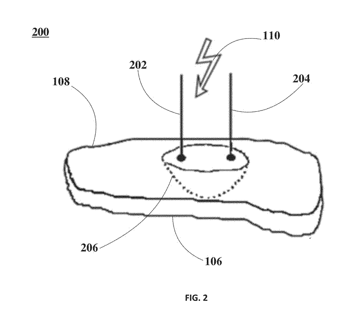
[0104]For these examples, four New Zealand rabbit hearts were isolated and placed in a Langendorff setup. Then, optical mapping was used to establish a control activation map during myocardial surface stimulation. Two shock electrodes were repeatedly inserted, spaced 25 mm apart, into the left ventricle through the entire wall. For the mapping of the heart about 50 pulses at about 1 Hz each were applied to electrodes using an intensity of about 0.52 kV / mm for about 300 ns. Additionally, propidium iodide stains were used to characterize the geometry of the ablated volume.

[0105]FIG. 8 includes photographic representations depicting a pulse application using a penetrating electrode configuration for ablation of myocardial tissue and incorporating nsPEFs, according to various embodiments.

[0106]FI...


PUM


Abstract

An apparatus and methods for performing ablation of myocardial tissues are disclosed. The apparatus includes a plurality of ablation electrode configurations to which nanosecond pulsed electric fields are applied. The methods relate to therapies to treat cardiac arrhythmias, such as, atrial fibrillation and scar-related ventricular tachycardia, amongst others. The affected myocardial tissues are ablated creating a plurality of lesions enabled by the nanosecond pulsed electric fields applied to either penetrating electrodes, endo-endo electrodes, or endo-epi electrodes. Different electrophysiological tests are performed to assess the application of nanosecond pulsed electric field ablation to specific desired tissue location within the heart. Test results show the potential to overcome limitations of current ablation therapies, thereby providing patients and doctors a superior treatment for cardiac arrhythmias.

Description

CROSS-REFERENCE TO RELATED APPLICATIONS[0001]This application is a continuation of U.S. application Ser. No. 14 / 604,400, filed Jan. 23, 2015 and entitled “Ablation of Myocardial Tissues with Nanosecond Pulsed Electric Fields”, which claims the benefit of U.S. Provisional Application No. 61 / 930,766 filed Jan. 23, 2014 and entitled “Nanosecond Pulsed Electric Fields Ablation”, the entire contents of which are incorporated herein by reference.BACKGROUNDField of the Disclosure[0002]The present disclosure relates generally to ablation, and more specifically, to systems and methods for biological tissue ablation using nanosecond pulsed electric fields.Background Information[0003]Four major types of radio frequency (RF) catheter ablation systems are currently used for treatment of myocardial tissues. These types of ablation systems are identified according to the type of catheters employed by each system. For example: (1) Standard 4-mm-tip catheters; (2) large 8-10-mm-tip catheters; (3) op...

Claims


Application Information

Patent Timeline
Patent Type & Authority Applications(United States)
IPC IPC(8): A61B18/14A61B18/00
CPCA61B18/1477A61B2018/00613A61B18/1492A61B2018/00363A61B2018/00357A61B2018/00577
Inventor ZEMLIN, CHRISTIAN W.
Owner OLD DOMINION UNIVERSITY RESEARCH FOUNDATION
Learn More