System and method for array antenna failure detection and antenna self-correction

Active Publication Date: 2018-06-21
NAT CHUNG SHAN INST SCI & TECH
View PDF3 Cites 3 Cited by
  • Summary
  • Abstract
  • Description
  • Claims
  • Application Information

AI Technical Summary

Benefits of technology

[0023]Hence, in the array antenna failure detection and antenna self-correction system according to the invention, a signal analyzer is employed to perform gain analysis so as to perform gain attenuation/compensation, and a DC offset generator is employed to generate a set of known offset amounts which are ad

Problems solved by technology

Since the channel evaluation information is associated with previous channel information, obtaini

Method used


Image

  • System and method for array antenna failure detection and antenna self-correction
  • System and method for array antenna failure detection and antenna self-correction
  • System and method for array antenna failure detection and antenna self-correction

Examples


Example

[0030]To better understanding of the above object, characteristics and effects of this invention, various embodiments will be taken with the attached drawings for the detailed description as follows.

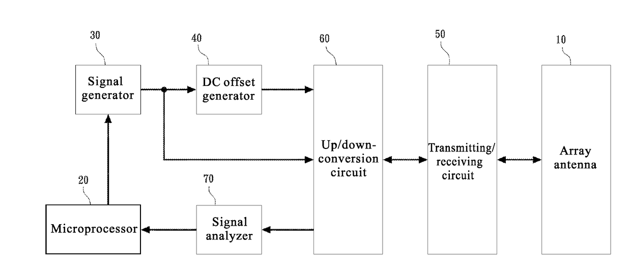
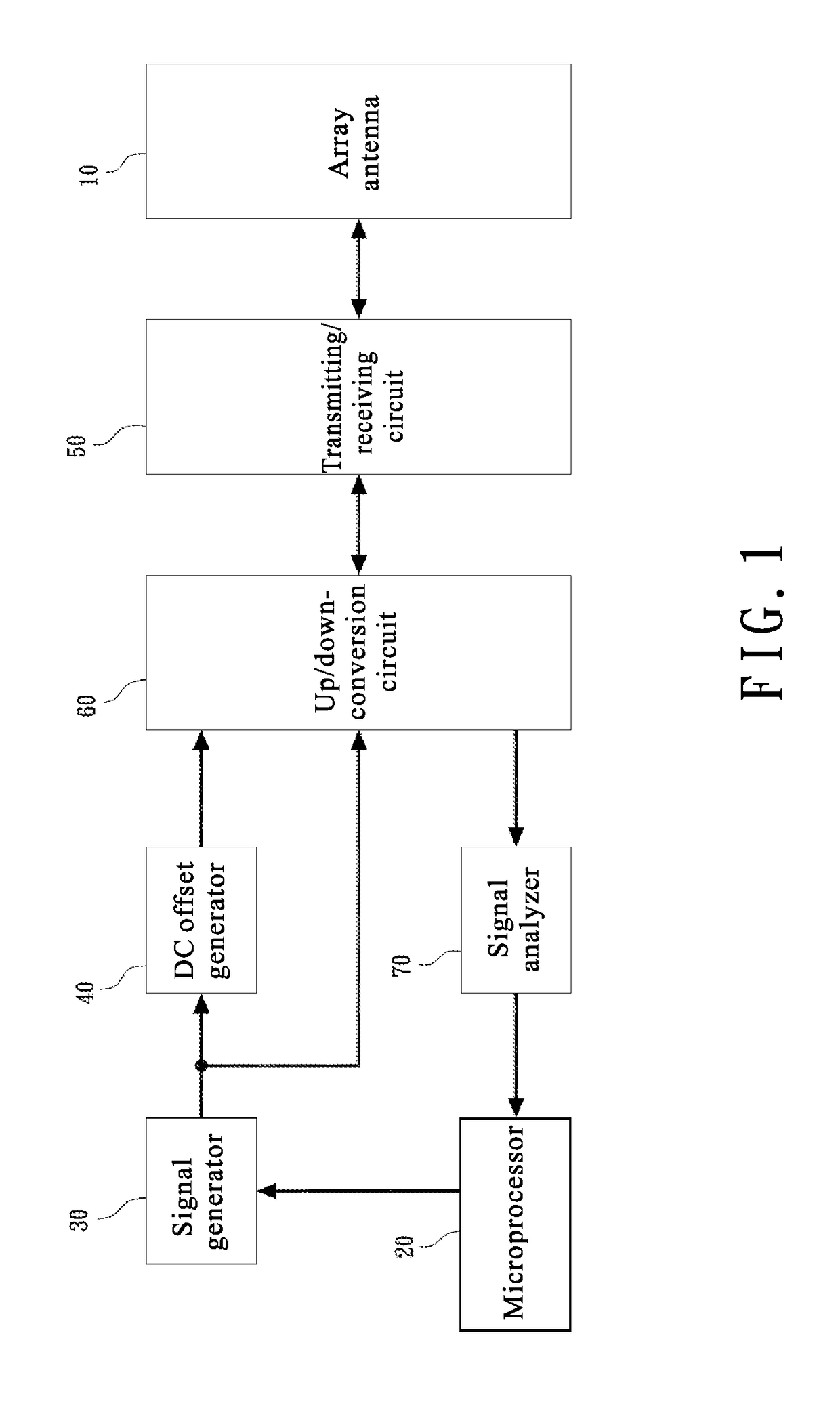
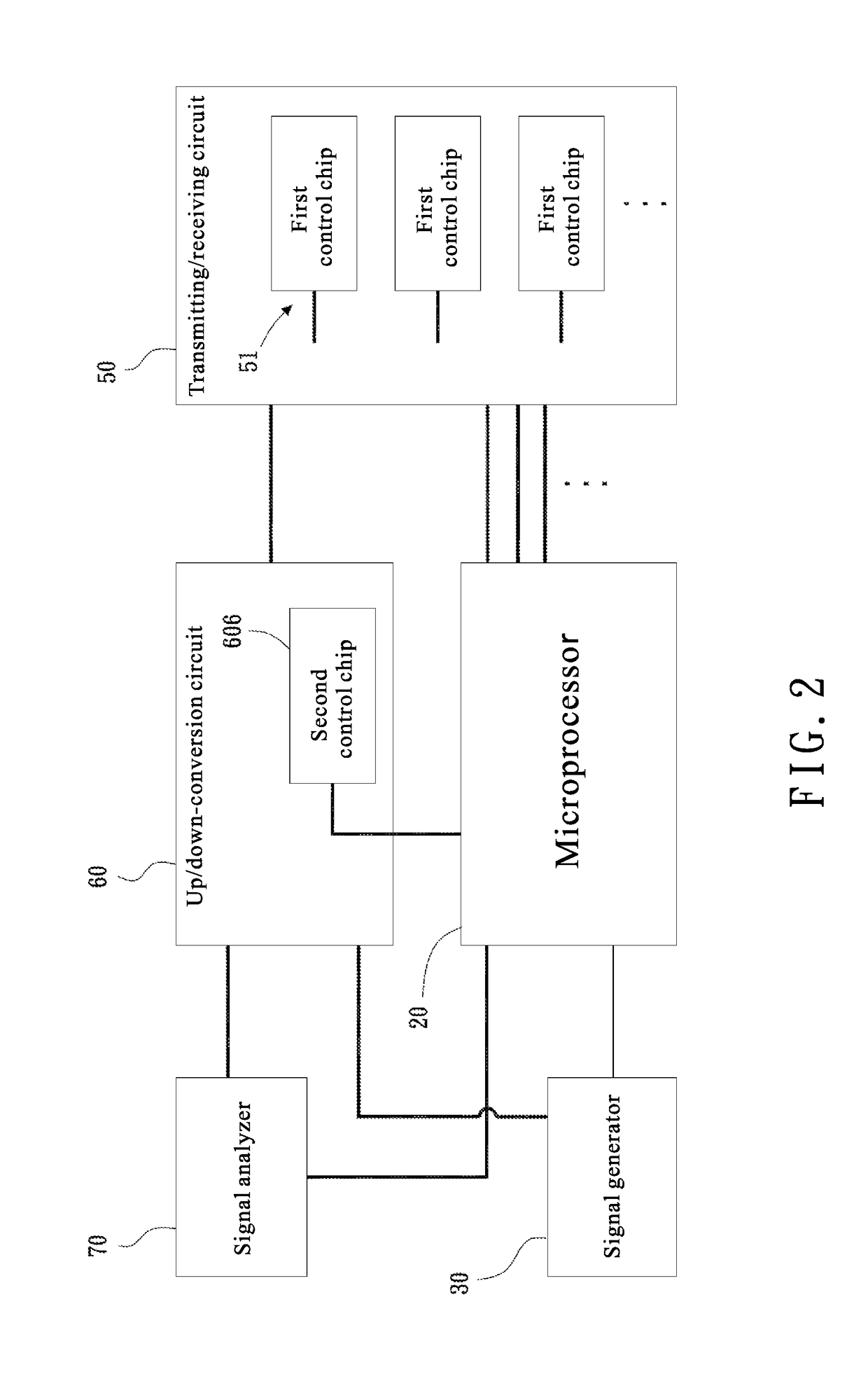
[0031]Referring to FIGS. 1 and 2, an array antenna failure detection and antenna self-correction system is illustrated according to an embodiment of the invention. As shown in the Figures, the system comprises: an array antenna 10, a microprocessor 20, a signal generator 30, a DC offset generator 40, a transmitting / receiving circuit 50, an up / down-conversion circuit 60, and a signal analyzer 70.

[0032]The array antenna 10 comprises at least one antenna unit to be tested 11 and a reference antenna, wherein the reference antenna is electrically coupled to the antenna unit to be tested 11, and the reference antenna can be used for generating a standard radiation pattern.

[0033]The microprocessor 20, electrically coupled to the signal generator 30, the transmitting / receiving circuit 50, the up...


PUM


Abstract

System and method for array antenna failure detection and antenna self-correction are introduced. In the array antenna failure detection and antenna self-correction system, a signal analyzer is employed to perform gain analysis so as to perform gain attenuation/compensation, and a DC offset generator is employed to generate a set of known offset amounts which are added to signals, so that, at the receiving end, a phase offset amount can be derived based on comparisons with the original signal, and antenna correction can then be performed accordingly. In this way, computational complexity of the system can be reduced, and the speed of antenna correction can be increased.

Description

FIELD OF THE INVENTION[0001]The present invention relates to wireless communication, and in particular to a system and a method for antenna failure detection and antenna self-correction.BACKGROUND OF THE INVENTION[0002]In the situations of failure of a transmitting / receiving module (T / R module) caused by degradation or other problem, phase modulation correction can be performed by analyzing the association between a reference antenna unit and an array antenna unit in order to have the detection to be performed in advance or reduce the detection cost, wherein the module cannot be sent back to the manufacturer for far-field test on the system. This is a possible solution of correction that is fast, simple, low-cost, and can be readily implemented.[0003]In the conventional techniques for phase modulation correction, channel evaluation information with respect to a plurality of forward links and reverse links is required for computation of phase deviation. Since the channel evaluation i...

Claims


Application Information

Patent Timeline
IPC IPC(8): H04B17/12
CPCH04B17/12H04L27/20H04L27/36H04B17/318
Inventor CHENG, CHU-HAOCHANG, PO-CHUNHUANG, LIANG-JU
Owner NAT CHUNG SHAN INST SCI & TECH
Why Eureka
Try Eureka