
Compact array of imaging devices with supplemental imaging unit

Active Publication Date: 2018-06-21
GOPRO
View PDF0 Cites 17 Cited by
  • Summary
  • Abstract
  • Description
  • Claims
  • Application Information

AI Technical Summary

Benefits of technology

This patent describes a system that uses a camera to capture depth information and construct a 3D reconstruction of a scene or video. The system can track objects in the camera and use this information to distinguish and isolate different objects in the video. This allows for easier stitching of video frames and improves image quality. The system can also use object tracking to position the camera and follow the movement of an object, as well as for image stabilization and focus locking. Overall, this system provides a powerful tool for analyzing and manipulating captured video.

Problems solved by technology

However, these imaging devices may need to be contained in compact housings, such as within smartphones.
These compact housing may not have sufficient depth to allow for a traditional camera with lens assembly that can support the enhanced features such as increased resolution.

Method used


Image

  • Compact array of imaging devices with supplemental imaging unit
  • Compact array of imaging devices with supplemental imaging unit
  • Compact array of imaging devices with supplemental imaging unit

Examples


example camera

Configuration

[0046]FIG. 3 is a block diagram illustrating electronic components of a camera 300, according to one embodiment. The camera 300 of the embodiment of FIG. 2 includes one or more microcontrollers 302, a system memory 304, a synchronization interface 306, a controller hub 308, one or more microphone controllers 310, an image sensor 312, a focus controller 314, one or more lenses 320, one or more LED lights 322, one or more buttons 324, one or more microphones 326, an I / O port interface 328, a display 330, an expansion pack interface 332, and a depth module 350. In one embodiment, the camera 300 may be one of the cameras 110 or the aux camera 115.

[0047]The camera 300 includes one or more microcontrollers 302 (such as a processor) that control the operation and functionality of the camera 300. For instance, the microcontrollers 302 can execute computer instructions stored on the memory 304 to perform the functionality described herein. It should be noted that although lookup...


PUM


Abstract

A method and system are described. The method includes capturing a set of images from a 2×2 array of cameras, each camera of the array of cameras having an overlapping field of view (FOV) with an adjacent camera of the array of cameras. The method further includes synchronously capturing a supplemental image from a fifth camera, the fifth camera having an at least partially overlapping FOV with every camera of the array of cameras. Supplemental information is extracted by comparing the supplemental image with the set of four images. Portions of the set of images are stitched based in part on the supplemental information to produce a combined stitched image, the combined stitched image having a higher resolution than each image of the set of images

Description

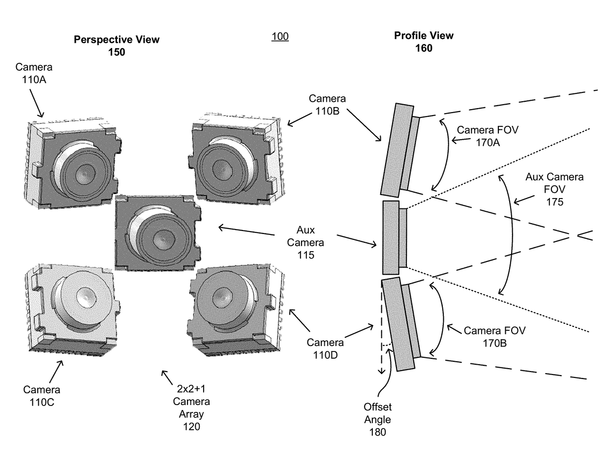
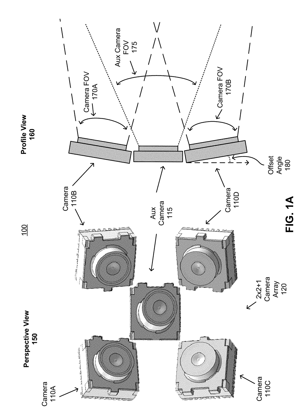
BACKGROUND1. Field of Art[0001]The disclosure generally relates to the field of imaging devices, and more particularly to an array of imaging devices with a supplemental imaging unit for improved image quality and functionality.2. Description of the Related Art[0002]New media formats and consumption paradigms have located a demand on imaging technology to develop higher fidelity imaging techniques that can provide more information about the environment captured by the imaging device. For example, the resolution requirements for captured images are increased to accommodate for applications such as virtual reality or wide field of view applications. However, these imaging devices may need to be contained in compact housings, such as within smartphones. These compact housing may not have sufficient depth to allow for a traditional camera with lens assembly that can support the enhanced features such as increased resolution. Hence, there is a need for an imaging device capable of produc...

Claims


Application Information

Patent Timeline
IPC IPC(8): H04N13/02G06K9/46G06T7/33G06T17/00G06T7/292H04N5/232G06V10/147
CPCG06K9/4609G06T7/33G06T17/00G06T7/292H04N5/23212H04N13/243G06T2207/10016H04N2013/0096H04N2213/003H04N13/296G06T2207/10028G06T3/4038H04N5/2624G06T3/4053G06V10/147G06V10/247H04N23/45H04N23/60H04N23/959H04N23/90G01S3/00
Inventor ABBAS, ADEELNEWMAN, DAVID A.MACMILLAN, TIMOTHY
Owner GOPRO
Learn More