Centralized seed distribution system for planter

Inactive Publication Date: 2002-04-18
KINZE MFG INC
View PDF0 Cites 21 Cited by
  • Summary
  • Abstract
  • Description
  • Claims
  • Application Information

AI Technical Summary

Benefits of technology

0018] When a wing section moves upwardly to adjust to ground contour, the inboard end of the tank is supported by the inboard pivot members located at the inboard end of the seed tank, and the horizontal link is in tension, resisting inward movement of the seed storage tank toward the center of the planter. This support structure and linkages for the seed storage tanks not only permits the tanks to move relative to the row units and the frame sections in order to accommodate variations in ground contour, but it reduces the amount of such motion and makes it possible to mount the seed tanks in low profile above the planter frame which is believed to be of considerable importance and value to the farmer, and it limits the number of seed storage tanks in a multi-section planter to two while increasing their storage capacity by permitting them to extend over, and be supported by, adjacent articulated frame sections.
0019] In this manner, the seed storage tank is permitted limited vertical movement relative to the articulated frame sections, and limited lateral movement, while adjusting to the hinging motions of the adjacent articulated frame sections during use. Moreover, each seed storage tank, one on the right side and one on the left side, is mounted for independent movement relative to the other seed storage tank so that they may independently accommodate the articulating motions of the left and right planter wing sections. Further, the total storage capacity of seed is greatly increased over individual hoppers on row units, and the number of storage tanks is limited to two. Because of the large size of the storage tanks and the large top opening in each seed storage tank, they are easily loaded by machine to reduce the loading time and effort.
0020] The seed storage tanks are received in, and mounted to, the U-shaped channels formed by the upright lattice frameworks and dual toolbar construction of the planter frame sections. This enables the seed tanks to have a low, attractive profile, yet provide a substantial volume for seed storage. A low tank profile has a number of advantages. First, a low tank profile provides safety features in that it does not interfere with overhanging gates or other structures when passing. Secondly, the farmer operator has an unobstructed view of the region behind the planter insofar as the height of the tanks is lower than the normal vision line of a farmer operator seated or standing on the tractor. Further, a substantial operational advantage is provided in that the center of gravity for the seed tanks is lower than if the tanks were located further above the planter frame. In addition, the seed storage tanks extend laterally and occupy substantially the entire width of the planter in the field use position. This distributes the weight of the seed tanks (which is substantial wh

Problems solved by technology

It is a very strenuous task to load eighteen empty or nearly empty hoppers using 50 lb. seed bags in the field.
The trend toward shipping in bulk containers, while reducing cost and saving time, has rendered the filling of individual seed tanks impractical due to difficulties in positioning the handling equipment and controlling the starting and stopping of the seed flow out of the bulk containers when desired, and without spillage.
Another disadvantage with individual seed hoppers is that i

Method used


Image

  • Centralized seed distribution system for planter
  • Centralized seed distribution system for planter
  • Centralized seed distribution system for planter

Examples


Example

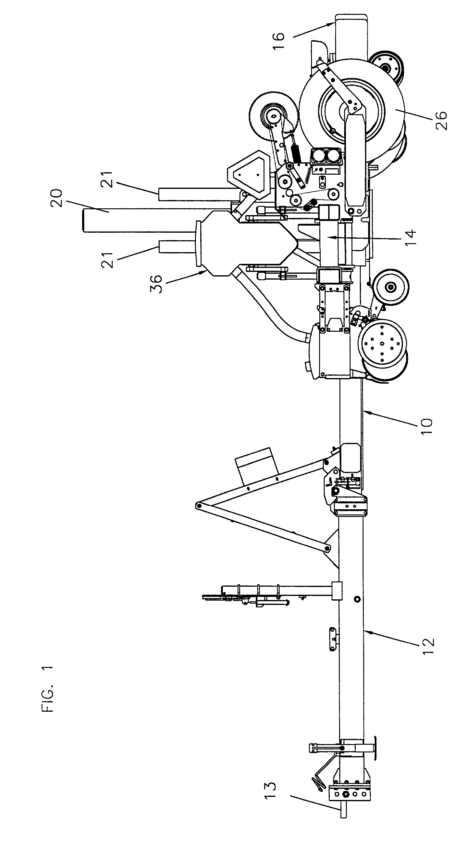
[0042] Referring first to FIG. 1, there is shown an agricultural row crop planter generally designated 10. The planter 10 includes an extendable hitch tongue generally designated 12 which is adapted to be connected to a tractor by means of a hitch 13. The tongue 12 is shown in FIG. 1 in the retracted position, but as known in the art, it may be extended or elongated so that a lift frame carrying the planter row units, to be described, and generally designated 14 may be raised from the field use position shown in FIG. 1 and turned ninety degrees (i.e., parallel to the plane of the page of FIG. 1) so that the planter lift frame extends longitudinally in the direction of travel of the tractor. This narrows the configuration for road transport.

[0043] The rear end of the tongue 12 is rigidly affixed to an axle assembly generally designated 16. The axle assembly 16 carries the main axle on which the ground support wheels 17 for the axle assembly and center frame section are mounted.

[0044]...


PUM


Abstract

An agricultural planter having left and right hinged wing sections includes seed storage tanks carried by the planter frame and feeding individual row units, mounted fore and aft of the main toolbar, by means of flexible conduits. The tanks are mounted to permit the wings to flex independently to follow ground contour while extending the tanks from a wing section onto the center frame section.

Description

[0001] This application, pursuant to 37 C.F.R. .sctn. 1.78(c), claims priority based on U.S. provisional application Ser. No. 60 / 218,230 filed on Jul. 14, 2000.[0002] The present invention relates to agricultural planters. Although the illustrated embodiment is in the form of an agricultural row crop planter having multiple frame sections which are hinged together to permit the planter to follow ground contour more closely, the invention has application to single frame planters and to grain drills as well. A row crop planter deposits individual seeds in rows. Typically, a row crop planter has a plurality of "row units" which are independently mounted to a pull frame. Each row unit forms a furrow, deposits separated or "singulated" seeds at a fixed spacing along the furrow and closes the furrow, covering the seed and lightly packing the soil above the seed.[0003] A planter row unit, in addition to having a furrow opening device, a seed meter or "singulating" mechanism for separating ...

Claims


Application Information

Patent Timeline
IPC IPC(8): A01C7/04A01C7/16A01C7/20
CPCA01C7/208A01C7/04
Inventor KINZENBAW, JON E.BARRY, ALAN F.DECKLER, HARRY C.
Owner KINZE MFG INC
Why Eureka
Try Eureka